 Global - English
 Spanish - Español
 French - Français
 Russian - Pусский язык
 Chinese - 中文
 Korean - 한국어
 Vietnamese - Tiếng Việt
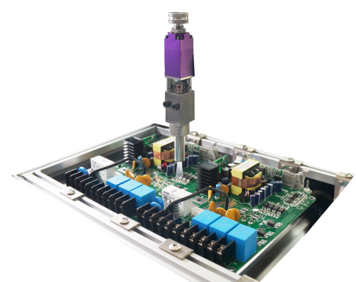
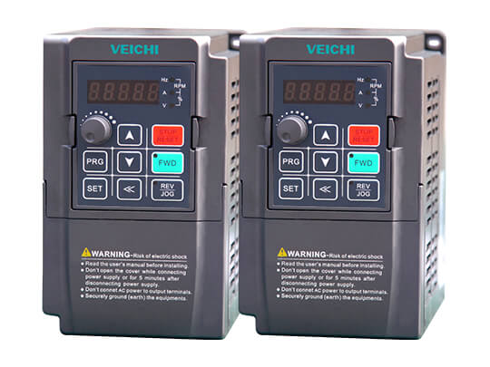
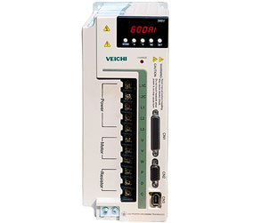
AC80B Medium Voltage Frequency Drives
- Specially designed on the platform of AC80, mature and stable.
- Professional design with optimized stucture, wiring method and etc.
- Strong anti-interference design and wide voltage range.
- Built-in DC reactor and grid-friendly.
AC80B medium voltage VFD drive is developed on the basis of advanced platform of AC80 that it has stable and high working performance. Below are its main features:
1. Professional Design
a. It is developed for the second time on the mature platform of AC80.
b. Designed with optimized structure that its stability and service life has been greatly improved.
c. In order to optimize the inner structure of control cabinet, all the models above 93KW adopts upper-input and bottom-output wiring method.
d. All the models above 30KW are all built-in with DC reactor in order to reduce the input harmonic, improve input power factor and protect your grid. All the series have been reserved with DC reactor connection terminal.
2. Strong Environmental Adaptability
a. All the standard products are painted with three-proofing lacquer which is imported from Germany. For the occasions of excessive humidity or dust, we provide special protection or treatment measures for the sake of meeting long-term stable running requirements in harsh environment.
b. It adopts air duct isolation technique which ensures it can work in severe industrial application environment.
c. For special applications, we can provide it to customers with sealed design.
3. Powerful Communication Function
a. It adopts international standard ModBus communication protocol. Users can set control command, running frequency, related parameters, status and more actions via PC, PLC, and master frequency converter to achieve centralized control, for meeting application requirements perfectly.
b. AC80B series support bus expansion, through options, it can even support the Profibus protocol.
4. Strong Anti-Interference Design
a. It supports wide working voltage range. When the voltage is low, it can guarantee the load capacity through modulation technique.
b. It meets industrial standards in power surge, power grid noise and static reactive immunity.
c. The control power and bus power has been separated. Control power adopts separate power supply via isolation transformer, and standard-designed filter circuit.
5. Powerful and Complete Protection Functions
Specifications
Below table displays the main technical specifications about AC80B VFD driver. If you need to learn more details such as the installations, fault diagnosis, function parameters and more, please navigate to the data download column to download its user manual to learn more.
|
Items |
Description |
|||
|
Power |
Voltage,frequency |
Single phase220V 50/60Hz; |
||
|
Allowable fluctuations |
Voltage:320V~440V; voltage unbalance rate: 3%; |
|||
|
Inrush current |
Lower than rated current |
|||
|
Power factor |
=0.94(with DC reactor) |
|||
|
Efficiency |
=96% |
|||
|
Output |
Output voltage |
Output under rated condition:3 phase, 0~input voltage, inaccurancy 5% |
||
|
Output frequency range |
G type:0-320Hz |
|||
|
Output frequency accuracy |
Max frequency ±0.5% |
|||
|
Overload capacity |
G type:150% rated current/1 min,180% rated current/10s, 200% rated current/0.5s |
|||
|
Main |
Motor control mode |
VC without PG, VC with PG, V/F without PG, V/F with PG |
||
|
Modulate mode |
Optimized SVPWM mode |
|||
|
Carrier frequency |
0.6~15.0kHz,randomized carrier-wave |
|||
|
Speed range |
VC without PG: rated load 1:100 |
|||
|
Steady speed accuracy |
VC without PG: =1% rated synchronized speed |
|||
|
Starting torque |
Flux VC without PG: when 0.5Hz, 180% rated torque |
|||
|
Torque response |
Flux VC without PG: =20ms |
|||
|
Torque control accuracy |
Flux VC without PG: ±10% |
|||
|
Frequency accuracy |
Digit setting:max frequency×±0.01% |
|||
|
Frequency resolution |
Digit setting:0.01Hz |
|||
|
Basic |
DC braking capacity |
Starting frequency:0.00~50.00Hz |
||
|
Torque upgrade capacity |
Auto torque upgrade 0.0%~100.0% |
|||
|
V/F curve |
5 modes: one user set V/F curve mode, one linearity torque characteristic curve and three drop torque characteristic curve (1.3power, 1.7power, 2.0 powers). |
|||
|
Acceleration/Deceleration curve |
2 modes: One linear Acceleration/Deceleration and two S curve Acceleration/Deceleration. Four sets of Acceleration/Deceleration time unit 0.01s selectable longest time: 650.00s. |
|||
|
Rated output voltage |
Rely on power supply voltage compensate function, while motor rated voltage is 100%, set it at the range of 50-100%(output can not over input voltge). |
|||
|
Voltage auto-adjust |
While power supply voltage fluctuates,it can auto-keep constant output voltage. |
|||
|
Energy-saving running |
According to load situation, auto-optimize output voltage to save energy. |
|||
|
Auto-limit current |
Auto-limit the current while running to prevent overcurrent break trouble. |
|||
|
Instant power off treatment |
While instant power off, realize continual operation by bus voltage control. |
|||
|
Standard functions |
PID control, speed track, power off restart, jump frequency, upper/lower frequency limit control, program operation, multi-steps speed, swing frequency running, RS485, analog output, frequency impulse output. |
|||
|
Frequency set channels |
Keyboard digital set, keyboard, potentionmeter, analog voltage terminal VS1/VS2, analog current terminal AS, communication given and multi channels terminal selection, master-slave channels combination. |
|||
|
Feedback input channel |
Voltage terminal VS1/VS2, current terminal AS, communication given, pulse input PUL. |
|||
|
Running command channel |
Operation panel given, external terminal given, communication given. |
|||
|
Input command signal |
Start, stop, FOR/REV, JOG, multi-step speed, free stop, reset, Acceleration/Deceleration time selection, frequency set channel selection, exterior fault alarm. |
|||
|
Exterior output signal |
One relay output, two collector output, 0~10V output,4~20mA output,frequency pulse output. |
|||
|
Protection function |
Overvoltage, undervoltage, current limit, overcurrent, overload, electric thermalrelay, overheat, overvoltage stall, data protection. |
|||
|
Keyboard |
LED display |
Single file 4 digital tube display |
Can monitor one state variable |
|
|
Two file 4 digital tube display |
Can monitor two state variables |
|||
|
Parameter copy |
Can upload or download function code information of inverter to realize fast parameter copy. |
|||
|
State monitor |
Output frequency, given frequency, output current, input voltage, output voltage, motor speed, PID feedback, PID given value, module temperature, input/output terminal condition. |
|||
|
Fault alarm |
Over-voltage, under-voltage, over-current, short circuit, open phase, overload, overheat, over-voltage speed lost, current limit, or data protection is destroyed; Fault running state; Fault history. |
|||
|
Environment |
Install place |
Indoor, altitude =1000m, no corrosive air or direct sunshine |
||
|
Temperature, |
-10 ~ +40? |
|||
|
Vibration |
Under 20Hz=0.5g |
|||
|
Store temperatue |
-25—+65? |
|||
|
Installation |
Hanging type, cabinet type |
|||
|
Protection |
IP20 |
|||
|
Cooling mode |
Forced cooling |
|||
Downloads
| File Name | Type | Language | File Type | Update | Download |
|---|---|---|---|---|---|
| Introduction of Internet of Things | Catalog | English | 2018-02-04 | 2.4MB | |
| AC70 Frequency AC Drive Manual V1.5 | Manual | English | 2024-02-28 | 9.81MB | |
| AC300 Series Frequency Inverter Manual V1.3.1 | Manual | English | 2020-10-13 | 3.08MB | |
| AC300 GSDML V2.31 and V2.35 | Software | English | ZIP | 2020-11-19 | 21.7KB |
| AC310 Series AC Drive Manual V1.6 | Manual | English | 2024-02-20 | 11.9MB | |
| VI20 USB Driver | Software | English | zip | 2023-05-23 | 8.07MB |
| Frequency Drive Catalog | Catalog | English | 2018-03-27 | 3.53MB | |
| Comprehensive Product Catalog of Renewable Energy | Catalog | English | 2021-03-16 | 15.4MB | |
| AC300 Series Frequency Inverter Catalog | Catalog | English | 2022-03-29 | 8.94MB | |
| Manual for AC100 Series Frequency Inverter V1.0 | Manual | English | 2018-03-05 | 5.9MB | |
| VC-4AD Analog Input Module User's Manual V1.0 | Manual | English | 2022-01-27 | 892KB | |
| VC1 PLC Manual V1.0 | Manual | English | 2022-01-27 | 839KB | |
| VC-4TC Thermocouple Type Temperature Input Module User Manual V1.0 | Catalog | English | 2022-01-27 | 807KB | |
| VC-4DA Analogue Output Module User Manual V1.0 | Manual | English | 2022-01-27 | 871KB | |
| VC PLC Programming Manual V1.1 | Manual | English | 2022-01-27 | 17.1MB | |
| VC Series Unpowered I/O Expansion Modules User Manual V1.0 | Manual | English | 2022-01-27 | 703KB | |
| VC RS485 Module Manual V1.0 | Manual | English | 2022-01-27 | 584KB | |
| VC-4PT Resistive Temperature Input Module User Manual V1.0 | Manual | English | 2022-01-27 | 923KB | |
| AC200 Series Frequency Inverter Maunal V1.3 | Manual | English | 2018-03-05 | 3.27MB | |
| CE (EMC) of SD700 Servo Drive | Certificate | English | 2018-07-06 | 283KB | |
| AC80C Inverter Manual V1.1 | Manual | English | 2018-03-05 | 5.3MB | |
| AC80C Inverter Catalog | Catalog | English | 2018-03-05 | 4.2MB | |
| AC70E Portable Mini Frequency AC Drive Manual V1.3 | Manual | English | 2018-03-05 | 1.3MB | |
| AC70E Portable Mini Frequency AC Drive Catalog | Catalog | English | 2018-03-05 | 1.2MB | |
| VC USB Driver V1.0 | Software | English | ZIP | 2022-01-27 | 1.99MB |
| Upper Computer Debugging Software V1.6.10 | Software | English | ZIP | 2022-01-27 | 18.6MB |
| CE (EMC) of AC300 Inverter | Certificate | English | 2018-07-06 | 284KB | |
| CE (LVD) of AC300 Inverter | Certificate | English | 2018-07-06 | 283KB | |
| SD500 Spindle Servo System Catalog EN V1.0 | Catalog | English | 2023-06-21 | 8.86MB | |
| VM Series PLC Remote Expansion Module V1.0 Catalog | Catalog | English | 2023-06-21 | 3.96MB | |
| System Control Solution of Air Compressor Catalog V1.0 | Catalog | English | 2022-03-29 | 16.6MB | |
| Quality Management System Certificate | Certificate | English | 2022-12-09 | 4.36MB | |
| VEICHI Products Catalog V1.0 | Catalog | English | 2023-06-05 | 67.7MB | |
| Company Profile of VEICHI | Catalog | English | 2018-05-18 | 5.3MB | |
| SD700 Series Servo Technical Manual V1.1 | Manual | English | 2022-04-21 | 9.04MB | |
| SI30 Solar Pump Inverter Manual V1.0 | Manual | English | 2019-09-17 | 1.39MB | |
| SIxV series BLDC Solar Pump System Catalog V1.0 | Catalog | English | 2022-01-27 | 18.8MB | |
| SIxV series BLDC Solar Pump System Manual V1.0 | Manual | English | 2022-01-27 | 4.58MB | |
| CE (LVD) of SD700 Servo Drive | Certificate | English | 2018-07-06 | 283KB | |
| CE (EMC) of SI23 Solar Pump Inverter | Certificate | English | 2018-07-06 | 277KB | |
| UL of V7U Servo Drive | Certificate | English | 2022-12-01 | 494.97 KB | |
| Servo Selector V1.0.6 (Simplifed for SD780)-EN | Software | English | ZIP | 2022-12-02 | 662KB |
| VEICHI Products Catalog Russian | Catalog | Russian | 2020-07-14 | 19.3 MB | |
| AC10 Series AC Drive Technical Catalog V1.2 | Catalog | English | 2024-02-20 | 3.03MB | |
| IEC of SI30 Solar Pump Inverter | Certificate | English | 2020-12-11 | 399kb | |
| CE (LVD) of SI23 Solar Pump Inverter | Certificate | English | 2018-07-06 | 277KB | |
| CE (EMC) of SI30 Solar Pump Inverter | Certificate | English | 2018-07-06 | 280KB | |
| CE (LVD) of SI30 Solar Pump Inverter | Certificate | English | 2018-07-06 | 280KB | |
| V5 Series PLC Instructions and Programming Manual V1.0 | Manual | 2019-12-23 | 4.72MB | ||
| AC70 Frequency AC Drive Catalog Brochure | Catalog | English | 2024-02-21 | 12.4MB | |
| VI20 101S FZ Specifications V1.0 | Manual | English | 2022-03-25 | 535KB | |
| CE (EMC) of SI20 D0 D1 D3 Solar Pump Inverter | Certificate | English | 2018-03-06 | 626KB | |
| SI23 Solar Pump Inverter Manual(detailed) V1.0 | Manual | English | 2023-10-20 | 9.15MB | |
| AC300 PC Debugging software V1.3 | Software | English | ZIP | 2019-05-05 | 11.38MB |
| S200C3 Construction Elevator Integrated Drive Catalog | Catalog | English | 2018-09-18 | 2.5MB | |
| VI10 Studio 20190429 EN | Software | English | ZIP | 2018-10-11 | 173MB |
| Smart Pump Drive Catalog V1.0 | Catalog | English | 2022-05-12 | 36.67MB | |
| Servo Selection Software v1.3 | Software | ZIP | 2020-07-20 | 587KB | |
| AC200-L Series Inverter Manual V1.2 | Manual | English | 2020-09-29 | 820KB | |
| SD700 Servo Drive Catalog V1.1 | Catalog | English | 2022-04-07 | 14.7MB | |
| CE (LVD) of SD650 Servo Drive | Certificate | English | 2018-03-06 | 626KB | |
| CE (EMC) of SD650 Servo Drive | Certificate | English | 2018-03-06 | 626KB | |
| SD650 Electro-hydraulic Servo Catalog | Catalog | English | 2018-03-06 | 1.3M | |
| SD600A-SMM Manual V1.0 | Manual | English | 2018-03-06 | 2.5MB | |
| Crane Solution Catalog | Catalog | English | 2024-04-10 | 4.64MB | |
| V5 SETUP V1.0.55 | Software | ZIP | 2020-08-11 | 36.4MB | |
| AC300 Series Profinet Manual V1.0 | Manual | English | 2020-11-23 | 2.10MB | |
| IN310 HVLS Fan Inverter Catalog | Catalog | English | 2021-08-30 | 2.41MB | |
| SD500 Spindle Servo Drive Instruction Manual V1.2-v1.3 | Manual | 2020-09-25 | 1.48MB | ||
| VI20 Studio 2.8.11635.0 for win7, win10 and win11 | Software | English | ZIP | 2023-05-29 | 859MB |
| SD710 Series Servo Technical Manual V1.0 | Manual | English | 2022-01-27 | 12.8MB | |
| SI22 Solar Pump Inverter Manual (Simplified) v1.0 | Manual | English | 2024-04-19 | 271KB | |
| VI20 Studio-2.8.11909.0 | Software | English | ZIP | 2024-02-20 | 938MB |
| ACDP01.GSD | Manual | English | ZIP | 2018-12-25 | 2KB |
| VEICHI DP card tutorial | Manual | English | ZIP | 2018-12-25 | 8.29MB |
| SD650 Electro-hydraulic Servo Manual | Manual | English | 2019-02-19 | 2.37MB | |
| VI20 User Manual V1.0 | Manual | English | 2022-03-25 | 29.1MB | |
| VI20 101S FE Specifications V1.0 | Manual | English | 2022-03-25 | 519KB | |
| VI20 070S FEZ Specifications V1.0 | Manual | English | 2022-03-25 | 532KB | |
| S200K lift integration special-purpose Manual V1.0 | Manual | English | 2019-03-28 | 2.71MB | |
| Solution for Machine Tool Industry | Catalog | English | 2019-04-17 | 10MB | |
| V5 Series PLC Instructions Simple Manual V1.0 | Manual | English | 2021-01-07 | 2.73MB | |
| AC70S Construction Hoist Specialized Inverter Manual V1.0 | Manual | English | 2022-04-08 | 812KB | |
| AC310 CAN EDS V1.0 | Software | English | ZIP | 2022-04-08 | 444KB |
| SI23 Solar Pump VFD Manual (Simplified )V1.0 | Manual | English | 2023-10-20 | 3.44MB | |
| VC.WIFI(V1.05) | Software | English | ZIP | 2022-09-20 | 2.26MB |
| SD700&710&780 Series Servo Soft V2.4-EN | Software | English | ZIP | 2023-03-15 | 51.8MB |
| AC300 Inverter Catalog - Russian | Catalog | Russian | 2019-07-26 | 1.24MB | |
| AC01 Network Type AC Drive Catalog | Catalog | English | 2024-02-29 | 4.08 MB | |
| AC300 Inverter Manual - Russian | Manual | Russian | 2019-07-26 | 1.6MB | |
| Lifting Industry (Gantry Crane) Catalog | Catalog | English | 2024-04-19 | 4.98M | |
| ACP30 Medium Voltage AC Drive Catalog | Catalog | English | 2024-03-21 | 5.04M | |
| AC90 Series Inverter Manual V1.1(VEICHI) | Manual | English | 2019-08-20 | 6.16MB | |
| AC100 Inverter Manual V1.0(VEICHI) | Manual | English | 2019-08-20 | 6.92MB | |
| SD700 Servo Drive Manual V1.4 | Manual | English | 2020-10-20 | 4.99MB | |
| SI Series Solar Inverter Catalog | Catalog | English | 2024-03-28 | 4.01MB | |
| VH Series Solar Inverter Catalog | Catalog | English | 2024-03-28 | 4.38MB | |
| Solar Panel Catalog | Catalog | English | 2024-03-28 | 4.12M | |
| SI30 Solar Pump Inverter Manual V1.2 | Manual | English | 2022-03-03 | 1.39MB | |
| VH600 Series General-purpose Medium PLC | Catalog | English | 2024-02-26 | 4.71MB | |
| VI20-FBOX Mobile App Download | Software | English | 2023-01-29 | 201KB | |
| AP100 Series Air Compressor User Manual V1.1 | Manual | English | 2020-04-16 | 3.10MB | |
| AC310 Series AC Drive Manual (Simplified) | Manual | English | 2024-03-13 | 1.33MB | |
| BU30 Brake Unit Manual v1.5 | Manual | English | 2022-04-26 | 996KB | |
| VI20 Studio 2.8.11635.0 for XP | Software | English | ZIP | 2023-05-29 | 885MB |
| SD700 Series Servo 3D Files | CAD File | English | ZIP | 2021-02-03 | 25.2MB |
| VM7 Servo Motor 3D Files | CAD File | English | ZIP | 2021-02-03 | 62.9MB |
| VM5 Servo Motor 3D Files | CAD File | English | ZIP | 2021-02-03 | 7.72MB |
| VI20 Series HMI Catalog | Catalog | English | 2023-10-23 | 25MB | |
| Electro-Hydraulic Servo Product Catalog | Catalog | English | 2022-03-29 | 20.3MB | |
| SD700 Servo Drive Catalog for Phone | Catalog | English | 2021-02-26 | 8.76MB | |
| SD700 Series Servo ECAT V1.1 G | Manual | English | ZIP | 2021-03-09 | 9.74KB |
| AC310 Series AC Drive Catalog V1.1 | Catalog | English | 2024-02-20 | 9.24MB | |
| AC Series Drive Software V1.6 | Software | English | ZIP | 2022-03-11 | 31.9MB |
| AC310 DP GSd V1.0 | Software | English | ZIP | 2022-04-27 | 2.64MB |
| Servo Selection(A1.7) V1.2 | Software | English | ZIP | 2022-06-17 | 812MB |
| V7E Servo Motor 3D | Software | English | ZIP | 2022-01-27 | 101MB |
| SI30 Solar Pump Inverter Manual V1.1 | Manual | English | 2024-04-19 | 3.61MB | |
| UL of SD780 Servo Drive | Certificate | English | 2022-12-01 | 492.23 KB | |
| VI20 101S FEZ Specifications V1.0 | Manual | English | 2022-03-25 | 529KB | |
| VI20 043S FZ Specifications V1.0 | Manual | English | 2022-03-25 | 301KB | |
| VI20 070S F Specifications V1.0 | Manual | English | 2022-03-25 | 517KB | |
| VI20 043S F Specifications V1.0 | Manual | English | 2022-03-25 | 275KB | |
| AC300 CAN EDS V1.0 | Software | English | ZIP | 2022-04-08 | 440KB |
| AC300 Profinet xml v1.0 | Manual | English | ZIP | 2022-04-20 | 2.38MB |
| SD700 Profinet xml V1.0 | Manual | English | ZIP | 2022-04-20 | 12.3MB |
| VI20 IOT BWS1.0 FLink Specification book V1.0 | Manual | English | 2022-04-20 | 488KB | |
| VI20 IOT BS4.0 FLink Specification V1.0 | Manual | English | 2022-04-20 | 548KB | |
| VI20-156S-FE Specification V1.0 | Manual | English | 2022-04-27 | 844KB | |
| AC310 Series AC Drive Manual Ru V1.0 | Manual | Russian | 2022-05-10 | 1.43MB | |
| VI20-Z Neutral Software V1.0 | Software | English | ZIP | 2022-06-10 | 695MB |
| SD700 Ethercat xml V1.0 | Manual | English | ZIP | 2022-05-17 | 3.88MB |
| MTS100 Module Test System Catalog | Catalog | English | 2023-06-02 | 1.31MB | |
| CTS100 Cell Test Equipment Catalog | Catalog | English | 2023-06-02 | 1.5MB | |
| An integrated water jet loom control system - utility model patent certificate | Certificate | Chinese | 2022-07-26 | 1.24MB | |
| VC600C electrical control all-in-one machine-appearance design patent certificate | Certificate | Chinese | 2022-07-26 | 1.17MB | |
| A weft detector and water jet loom system - invention patent certificate | Certificate | Chinese | 2022-07-26 | 1.21MB | |
| SD780 Series Servo Drive User Manual V1.0 | Manual | English | 2022-07-29 | 17.0MB | |
| CE (LVD) of V7E&V7U&VM7 Servo Motor | Certificate | English | 2022-12-19 | 296KB | |
| VC Programming Software V1.3 | Software | English | ZIP | 2022-12-19 | 53.9MB |
| VI20-FBOX-FlexManager-1.0.3131.0 | Software | English | ZIP | 2023-01-29 | 93.3MB |
| EV Series Electric Vehicle Motor Controller Catalog | Catalog | English | 2023-06-12 | 4.47MB | |
| EtherCAT Motion Control User Manual V1.0 | Manual | English | 2023-02-23 | 17MB | |
| VC Series PLC Basic Programming Manual V1.0 | Manual | English | 2023-02-23 | 24.6 MB | |
| VC-4DA Quick Reference Manual V1.0 | Manual | English | 2023-02-23 | 859KB | |
| VC-4PT Quick Reference Manual V1.0 | Manual | English | 2023-02-23 | 911KB | |
| VC-4TC Quick Reference Manual V1.0 | Manual | English | 2023-02-23 | 794KB | |
| VC-eNET User Manual V1.0 | Manual | English | 2023-02-23 | 815KB | |
| VC-IO Quick Reference Manual_V1.0 | Manual | English | 2023-02-23 | 691KB | |
| VC-RS485 Module Quick Reference Manual V1.0 | Manual | English | 2023-02-23 | 576KB | |
| VC-24V5POW User Manual V1.0 | Manual | English | 2023-02-23 | 669KB | |
| VC-4AD User Manual V1.0 | Manual | English | 2023-02-23 | 880KB | |
| VC Programming Software V1.12.7.3 | Software | English | zip | 2023-05-29 | 54.2MB |
| SD500 Spindle Servo Drive Manual (Simple) V1.4 | Manual | English | 2023-06-27 | 2.39MB | |
| SD100 Series Low-voltage Servo System Catalog V1.0 | Catalog | English | 2023-07-14 | 3.42MB | |
| AC01 Network Type AC Drive Manual V1.1 | Manual | English | 2023-12-26 | 1.64 MB | |
| AC70T Crane Purpose AC Drive Manual V1.5 | Manual | English | 2023-12-14 | 5.81M | |
| VC5 Series PLC Custom Variable Manual V1.0 | Manual | English | 2023-08-02 | 1.14M | |
| SD100 Servo Drive Manual V1.2 | Manual | English | 2023-11-27 | 12.6M | |
| SD700 User Manual V1.0 | Manual | English | 2023-08-03 | 10.4M | |
| AC series upper computer debugging software V1.6.20 | Software | English | ZIP | 2024-02-20 | 46.5M |
| PLC Soft_setup_V1.12.8.1 | Software | English | ZIP | 2023-08-08 | 56.2M |
| AC310 Repair Manual V1.0 | Manual | English | 2023-12-14 | 3.95M | |
| PLC Soft_Setup_V1.12.8.5 | Software | English | ZIP | 2023-08-10 | 56.3M |
| AC70T Communication Card Manual V1.0 | Manual | English | 2023-12-14 | 656K | |
| SIS Series Off Grid Solar Inverter Manual | Manual | English | 2023-10-18 | 1.83M | |
| VC5 Ethercat Motion Control Manual V1.0 | Manual | English | 2023-08-17 | 16.3M | |
| VC5 Series PLC Custom Variable Manual V1.0 | Manual | English | 2023-08-17 | 1.47M | |
| VEICHI firmware upgrade V3.4.11 | Software | English | ZIP | 2023-09-07 | 1.91M |
| AC01 AC Drive 3D Files | CAD File | EN | ZIP | 2023-11-13 | 89.5M |
| BLDC Solar Water Pump Catalog V1.0 | Catalog | English | 2023-09-11 | 7.23M | |
| VCACSoft AC800_12 V2.1.10 | Software | EN | ZIP | 2023-11-08 | 15.1M |
| VM Series Expansion Module Manual V1.0 | Manual | English | ZIP | 2023-10-07 | 11.7MB |
| PLC Soft_Setup_V1.12.8.6 | Software | English | ZIP | 2023-10-07 | 56.5M |
| SD700 EtherCAT Communication Manual V1.0 | Manual | English | 2023-10-07 | 5.19M | |
| SD700 Fault Description EtherCat V1.0 | Manual | English | 2023-10-07 | 132KB | |
| SIS Series Hybrid Solar Inverter Manual | Manual | English | 2023-10-18 | 5.84M | |
| SIS1 Series Off Grid Solar Inverter Manual | Manual | English | 2023-10-18 | 5.76M | |
| SIS1 Series Hybrid Solar Inverter Manual | Manual | English | 2023-10-18 | 6.26M | |
| SIS4 Series Off Grid Solar Inverter Manual | Manual | English | 2023-10-18 | 12.3M | |
| SISV Series Off Grid Solar Inverter Manual | Manual | English | 2023-10-18 | 15.5M | |
| SISV Series Hybrid Solar Inverter 4.2K-6.2K Manual | Manual | English | 2023-10-18 | 19.5M | |
| SISV Series Hybrid Solar Inverter 7.2K Manual | Manual | English | 2023-10-18 | 18.4M | |
| SIT Series IP65 Hybrid Solar Inverter 12K-15K Manual | Manual | English | 2023-10-18 | 6.4M | |
| SIT Series IP65 Hybrid Solar Inverter 30K Manual | Manual | English | 2023-10-18 | 1.47M | |
| SI21 Solar Pump VFD Manual (Simplified)V1.0 | Manual | English | 2023-10-20 | 1.15MB | |
| SI21 Solar Pump VFD Manual (Details)V1.0 | Manual | English | 2023-10-20 | 7.8MB | |
| VI20 Studio-2.8.11777.0 | Software | English | ZIP | 2023-10-23 | 895MB |
| HMI FGateManager-1.0.3289.0 | Software | English | ZIP | 2023-10-23 | 114MB |
| ACH200 High Voltage AC Drive Manual V1.0 | Manual | English | 2023-11-24 | 7.4M | |
| ACH200 High Voltage AC Drive Catalog V1.0 | Manual | English | 2023-11-24 | 11.6M | |
| SD100 Servo Drive Catalog V1.2 | Catalog | English | 2023-12-22 | 4.11M | |
| AC310 Series AC Drive Catalog Fr V1.1 | Catalog | French | 2023-12-13 | 7MB | |
| AC310 Series AC Drive Catalog Gr V1.1 | Catalog | German | 2023-12-14 | 9.71MB | |
| AC310 Series AC Drive Catalog It V1.1 | Catalog | Italian | 2023-12-14 | 9.39MB | |
| AC310 Series AC Drive Catalog Sp V1.1 | Catalog | Spanish | 2023-12-14 | 4.8MB | |
| Servo Selection V1.0.8 | Software | English | ZIP | 2023-12-14 | 652KB |
| AC10 Series Frequency AC Drive Technical Manual V1.7 | Manual | English | 2023-12-26 | 12.7M | |
| SD Soft V1.12.12-20240120 | Software | English | ZIP | 2024-02-20 | 44.6MB |
| SD700 Safety Torque Off Manual | Manual | English | 2024-01-03 | 671KB | |
| Solar Water Pump Inverter Catalog | Catalog | English | 2024-03-07 | 5.16MB | |
| VM Series PLC Flexible Remote Module Catolog V1.1 | Catalog | English | 2024-01-22 | 5.71MB | |
| VC1-0808MAT1 PLC Quick Reference Manual V1.0 | Manual | English | 2024-01-22 | 764KB | |
| VC1-0808MAR1 PLC Quick Reference Manual V1.0 | Manual | English | 2024-01-22 | 766KB | |
| VC1-1616MAR-T PLC Quick Reference Manual V1.0 | Manual | English | 2024-01-22 | 718KB | |
| VC1-2424MAM-4TC PLC Quick Reference Manual V1.0 | Manual | English | 2024-01-22 | 676KB | |
| PLC Series Catalog | Catalog | English | 2024-03-28 | 8.06MB | |
| Wall Mounted LiFePO4 Battery User Manual V1.0.pdf | Manual | English | 2024-01-22 | 1.22M | |
| CH310E Elevator Drive Catolog | Catalog | English | 2024-02-02 | 5.05M | |
| Energy Storage Battery Catalog | Catalog | English | 2024-03-28 | 3.31M |


 Leave a Message