 Global - English
 Spanish - Español
 French - Français
 Russian - Pусский язык
 Chinese - 中文
 Korean - 한국어
 Vietnamese - Tiếng Việt
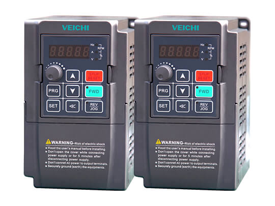
AC300 Series Frequency Inverter
- High-performance vector general platform & brand-new motor control algorithm
- Integrated PMSM & AM drive & comprehensive open-loop and closed-loop
- Book design saves installation space
- Up-down straight air-duct design & DC fan cooling
AC300 Series High Performance Inverter Overview
VEICHI AC300 series inverter is the product developed on the platform of VEICHI latest high-performance vector technology. It not only adopts the internationally leading filed-orientation vector control technology, which is compatible with AM and PMSM control, but also makes the most reasonable layout of components under the premise of high-performance and high-reliability, so as to achieve the book narrow-body design. Besides, to strengthen the usability and industrial specialization, it is equipped with rich extension interfaces and new extension accessories, realizing the features of high performance, high reliability, high power density and high usability.
AC300 VFD features
1. High-performance vector universal platform, brand new motor control algorithm.
2. Synchronous and asynchronous drives are integrated, open loop and closed loop are comprehensive.
3. Software and hardware modular design requirements, strong expansion capabilities.
4. Rich interface accessories, covering various applications.
5. Book design, save installation space.
6. Optimize the convenient keyboard design, support the new external keyboard.
7. The upper and lower straight ventilation ducts are designed to dissipate heat by DC fans.
8. PCB spraying three-proof paint to ensure product stability and reliability.
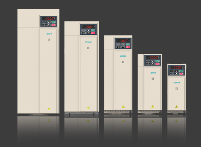
New appearance, design, and aesthetics are integrated
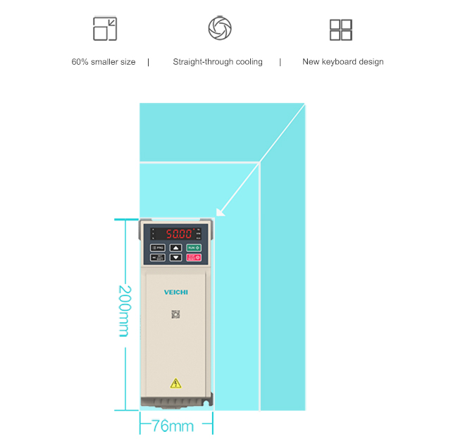
1. Book-style narrow body structure design reduces the volume by 60%.
2. Up and down straight-through heat dissipation, multiple inverters can be installed side by side, greatly reducing the volume of the electrical cabinet.
3. New keyboard design, simple appearance, support dual keyboard display.
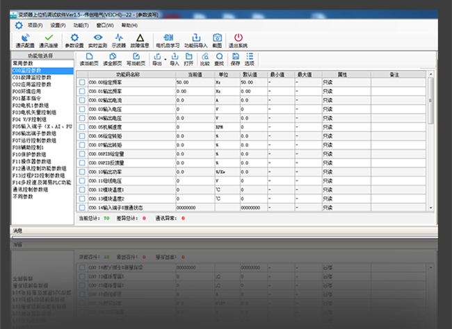
Make it simple, save more than time
1. European-style terminal, simple wiring, improve efficiency.
2. Domestic general parameter arrangement, optimized operation buttons, easy to use.
3. Dedicated upper debugging software VCACSoft Ver1.5 reduces debugging time and difficulty.
Ingenious control algorithm
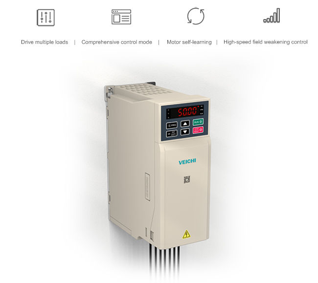
1. Drive a variety of loads: support synchronous, asynchronous, electric spindle, AC servo, and other motors.
2. Control mode: One machine covers V/F mode, frequency separation, open/closed-loop vector, free selection of speed and torque.
3. Motor self-learning: self-learning algorithm, accurate and consistent movement, and static.
4. High-speed field weakening control: high bandwidth current vector, 12 times the field weakening high precision output.
Hardcore style, reliable protection
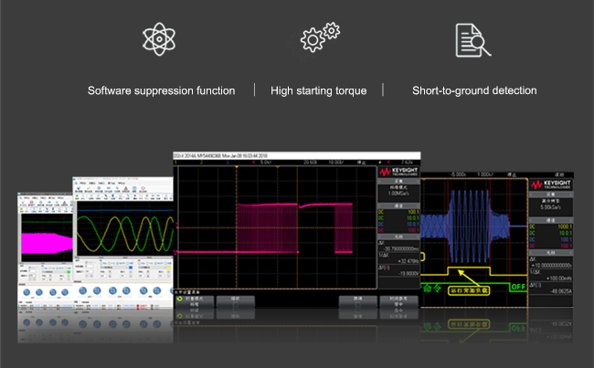
1. Software suppression function: over-current, over-voltage fast response, stable suppression.
2. High starting torque: large low-frequency torque, ultra-low speed, and stable load operation without alarm.
3. Short-circuit detection to the ground: Realize protection from the inverter to the motor.
Exquisite structure, handy in harsh environments
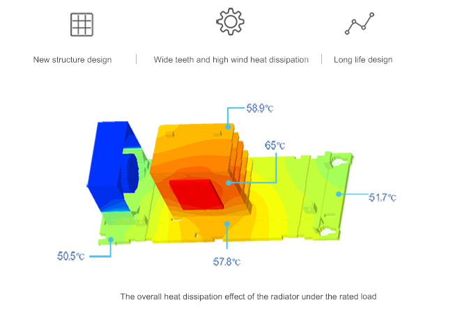
1. New structural design: separate design of device and air duct, closed design on both sides of the machine, improve the machine's environmental resistance.
2. Wide-tooth high-wind heat dissipation: wide-tooth surface high-efficiency heat dissipation, high-volume, and high-speed cooling fan to ensure no derating at high temperatures in the full power section.
3. Long-life design: Strict selection of high-quality parts, scientific layout, effectively avoid the occurrence of excessive-high temperature and extend the product life cycle.
Everything is available, with rich expansion capabilities
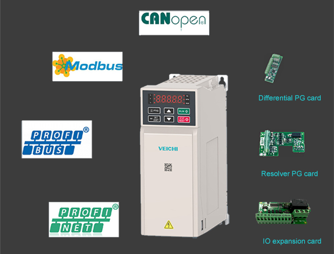
1. SPI expansion port, automatic identification of expansion card, high-speed channel optimization efficiency.
2. Abundant extensions: support multiple types of sub-expansion cards, diverse functions, suitable for multiple occasions.
Do more with less, and new debugging tools came into being
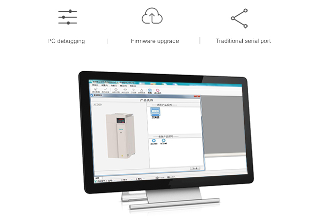
1. Host computer debugging: VCACSoft Ver1.5 is easy to operate, configure parameters, and provide customers with flexibility.
2. Firmware upgrade: the built-in software can be directly upgraded and replaced online, reducing maintenance and replacement costs.
3. Traditional serial port: commonly used RS485 interface or field bus for data exchange.
Industrial Applications for AC300 Series frequency inverter
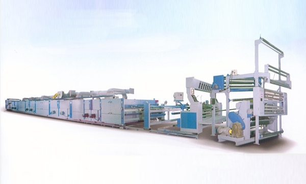
Application: Mining, CNC, hoisting, chemical engineering, ceramics, petroleum and petrochemical, municipal engineering, printing and packaging, wire and cable and other industries and equipments.
AC300 frequency drive Video
Related Applications of AC300 Frequency Drive
Application of AC300 in Synchronous Drive Control System
Application of AC300 in Synchronous Transmission Control System
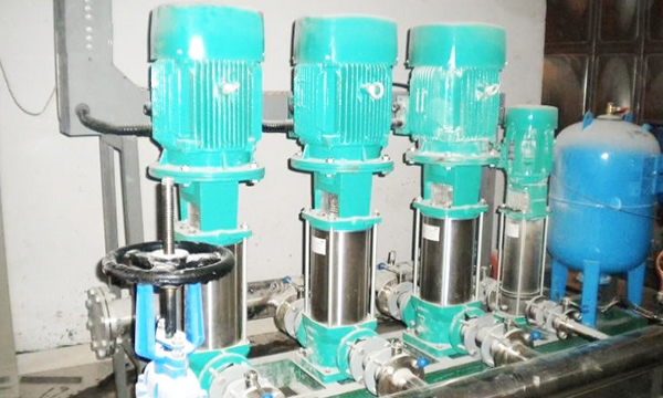
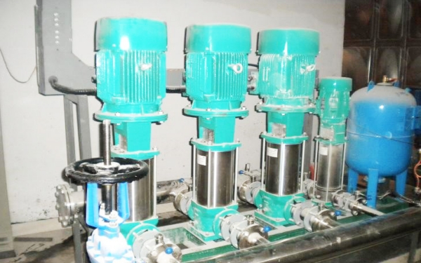
Application of AC300 frequency converter in water supply industry
Application of AC300 General Frequency Inverter on Power-Discharging Rack
AC300 series inverter used on stereo garage
Specifications
| Single phase 220V 50/60Hz | 0.75kW - 220kW |
|---|---|
| Three phase 220V 50/60Hz | 0.75kW - 220kW |
| Three phase 380V 50/60Hz | 0.75kW - 710kW |
| Voltage and frequency | 3-phase 380V, 50/60Hz |
|---|---|
| Allowed fluctuation range | Voltage unbalance ratio:<3%; Frequency fluctuation: ±5%;Distortion rate: conform to IEC 61800-2 |
| Switching impulse current | Lower than rated current |
| Power factor | ≥0.94 (DC reactor) |
| Frequency inverter efficiency | ≥96% |
| Output voltage | Output under rated condition: 3 phase, 0~input voltage, deviation<5% |
|---|---|
| Output frequency range | G type:0~600Hz |
| Output frequency accuracy | Max frequency ±0.5% |
| Overload capacity | G type: 150% rated current/1 min, 180% rated current/10s, 200% rated current/0.5s P type: 120% rated current/1 min, 140% rated current/10s, 150% rated current/0.5s |
| Motor control mode | V/F control without PG, vector control without PG, V/F control with PG, vector control with PG |
|---|---|
| Modulation method | Optimized space vector PWM modulation |
| Carrier frequency | 0.7~16.0kHz |
| Speed control range | Vector control without PG, rated load 1:100; Vector control with PG, rated load 1:1000 |
| Speed accuracy in steady | Vector control without PG: ≤ 2% rated synchronous speed; Vector control with PG: ≤ 0.05% rated synchronous speed |
| Starting torque | Vector control without PG: 150% rated torque at 0.5Hz; Vector control with PG: 200% rated torque at 0Hz |
| Torque response | Vector control without PG: <20ms; Vector control with PG: <10ms |
| Frequency accuracy | Digital setting: maximum frequency × ± 0.01%; Analog setting: maximum frequency × ± 0.2% |
| Frequency resolution | Digital setting: 0.01Hz; analog setting: maximum frequency × 0.05% |
| DC braking capability | Starting frequency: 0.00~50.00Hz; Braking time: 0.0~60.0s; Braking current: 0.0~150.0% of rated current |
|---|---|
| Torque boost | Automatic torque boost: 0.0%~100.0%; Manual torque boost: 0.0%~30.0% |
| V/F curve | Four methods: linear torque characteristic curve, self-setting V/F curve, drop-torque characteristic curve (1.1~2.0th power), squared V/F curve |
| Acceleration/Deceler ation curve | Two methods: linear acceleration/deceleration and S-curve acceleration/deceleration Four sets of acceleration and deceleration time, time unit-0.01s, longest time-650.00s |
| Rated output voltage | Using the power supply voltage compensation function, the rated voltage of the motor is 100%, which can be set in the range of 50 to 100% (the output cannot exceed the input voltage). |
| Automatic voltage adjustment | When the voltage fluctuates, the output voltage is automatically maintained |
| Automatic energy-saving operation | Automatically optimize output voltage according to load in V/F control mode to achieve energy-saving operation |
| Automatic current limiting | Automatically limit current during operation to prevent frequent overcurrent fault tripping |
| Instant power-off processing | Uninterrupted operation through bus voltage control when instantaneous power-down |
| Standard function | PID control, speed tracking and restart after power-down, jump frequency, frequency upper and lower limit control, program operation, multi-step speed, RS485, analog output, frequency pulse output. |
| Frequency setting channel | Keypad digital setting, analog voltage/current terminal AI1, analog voltage/current terminal AI2, communication given and multi-channel terminals selection, main and auxiliary channel combination, expansion card, can be switched by various ways. |
| Feedback input channel | Voltage / current terminal AI1, voltage / current terminal AI12, communication given, low-speed pulse input PUL, expansion card. |
| Run command channel | Operation panel given, external terminal given, communication given, expansion card given |
| Input command signal | Start, stop, forward/reverse, jog, multi-speed, free stop, reset, acceleration/deceleration time selection, frequency setting channel selection, external fault alarm. |
| External output signal | 1 relay output, 1 collector output, and 1 AO output can be selected as 0~10V or 4~20mA or frequency pulse output. |
| Protective function | Over-voltage, under-voltage, current limit, over-current, overload, electronic thermal relay, over-heat, over-voltage stall, data protection, fast-speed protection, input and output loss phase protection. |
|---|
| LED display | Single-line 5-bit digital display, monitors 1 frequency inverter status value Dual-line 5-bit digital display, monitors 2 frequency inverter status value |
|---|---|
| Copy of parameters | Can upload and download the function code information of the frequency inverter to achieve fast copy of parameters |
| Condition monitoring | All parameters of monitoring parameter group such as output frequency, given frequency, output current, input voltage, output voltage, motor speed, PID feedback, PID given quantity, module temperature, etc. |
| Faults alarm | Over-voltage, under-voltage, over-current, short circuit, loss phase, overload, over-heat, over-voltage stall, current limit, data-damaged protection, current operation fault, historical faults. |
| Installation location | The altitude should be less than 1000 meters and the rated power is reduced to use when the altitude is above 1000 meters, and the depreciation is 1% for every 100 meters increment. No condensation, icing, rain, snow, haze, etc., solar radiation is below 700W/m2, air pressure is 70~106kPa. |
|---|---|
| Temperature and humidity | -10 ~ +50°C, derating can be used above 40 °C, the maximum temperature is 60 °C (no-load operation), 5%~95%RH(no condensation) |
| Vibration | 9~200Hz, 5.9m/s2(0.6g) |
| Storage temperature | -30~+60℃ |
| Installation mode | Wall-mounted type, cabinet type |
| Protection degree | IP20 |
| Cooling method | Forced air cooling |
Downloads
| File Name | Type | Language | File Type | Update | Download |
|---|---|---|---|---|---|
| Introduction of Internet of Things | Catalog | English | 2018-02-04 | 2.4MB | |
| AC300 Series Frequency Inverter Manual V1.3.1 | Manual | English | 2020-10-13 | 3.08MB | |
| AC300 GSDML V2.31 and V2.35 | Software | English | ZIP | 2020-11-19 | 21.7KB |
| AC300 Series Frequency Inverter Catalog | Catalog | English | 2022-03-29 | 8.94MB | |
| CE (EMC) of AC300 Inverter | Certificate | English | 2018-07-06 | 284KB | |
| CE (LVD) of AC300 Inverter | Certificate | English | 2018-07-06 | 283KB | |
| AC300 PC Debugging software V1.3 | Software | English | ZIP | 2019-05-05 | 11.38MB |
| AC300 Series Profinet Manual V1.0 | Manual | English | 2020-11-23 | 2.10MB | |
| VEICHI DP card tutorial | Manual | English | ZIP | 2018-12-25 | 8.29MB |
| AC300 Inverter Catalog - Russian | Catalog | Russian | 2019-07-26 | 1.24MB | |
| AC300 Inverter Manual - Russian | Manual | Russian | 2019-07-26 | 1.6MB | |
| AC Series Drive Software V1.6 | Software | English | ZIP | 2022-03-11 | 31.9MB |
| AC300 CAN EDS V1.0 | Software | English | ZIP | 2022-04-08 | 440KB |
| AC300 Profinet xml v1.0 | Manual | English | ZIP | 2022-04-20 | 2.38MB |


 Leave a Message