 Global - English
 Spanish - Español
 French - Français
 Russian - Pусский язык
 Chinese - 中文
 Korean - 한국어
 Vietnamese - Tiếng Việt
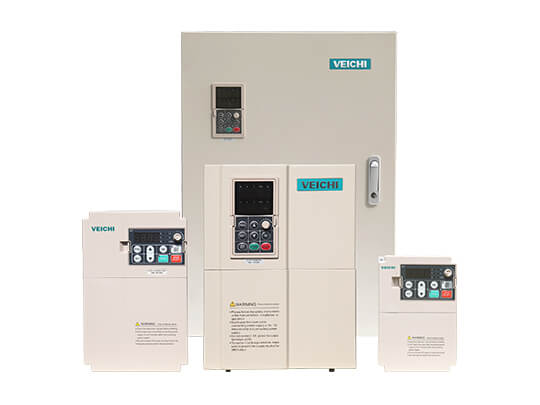
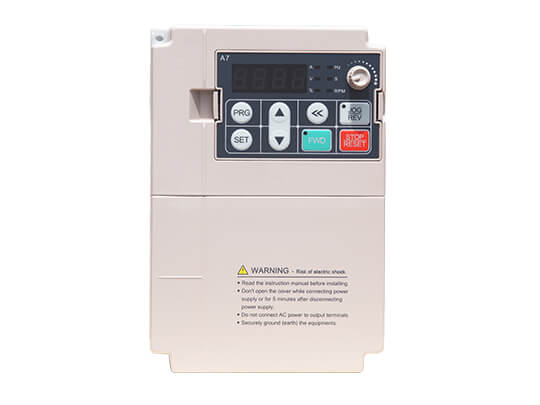
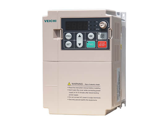
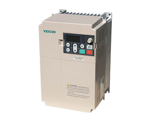
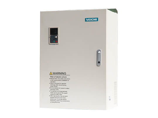
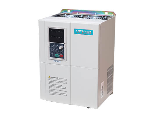
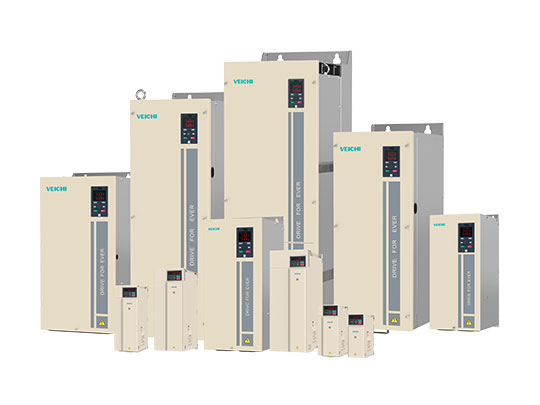
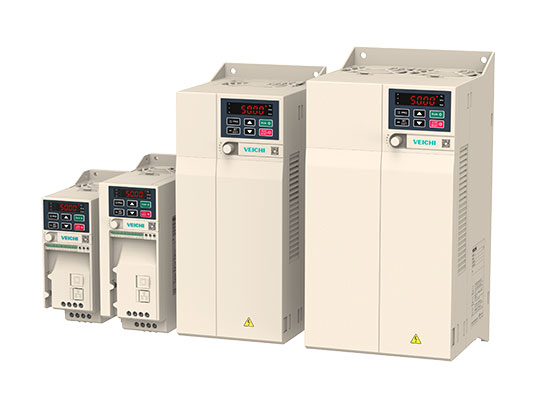
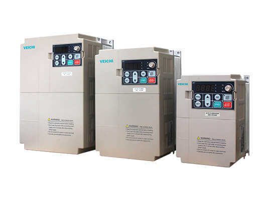
AC200 High Performance Vector Control AC Drive
- Adopting high-performance vector control algorithm
- Unique synchronous motor control algorithm
- Excellent impact load response capability
- Over-excitation function, no external braking resistor required
AC200 High Performance Vector Control AC Drive Overview
While maintaining excellent performance and functions, AC200 series products have been significantly improved in terms of ease of use, maintainability, environmental protection, installation space, and design standards from the perspective of customer applications.
AC200 general-purpose inverter——with improved functions and advanced technology
1. Compact structure and easy to use.
2. Integration of driving synchronous and asynchronous motors.
3. High starting torque, open loop 0.5Hz 150%, closed loop 0Hz 200% rated torque.
4. High-frequency output, 12 times magnetic field weakening speed range, high precision output.
5. Excellent control performance.
6. Advanced motor self-learning function.
7. Extensive functions are abundant.
8. Simple debugging software.
One machine with multiple functions, widely used
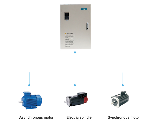
1. Supports various types of motors/loads and can drive motors: ordinary asynchronous motors, variable frequency motors, AC servo motors, synchronous motors, high-speed motors and electric spindles.
2. Supports various types of motors/loads and can drive motors: ordinary asynchronous motors, variable frequency motors, AC servo motors, synchronous motors, high-speed motors, and electric spindles.
Quick start and stop, smooth and stable
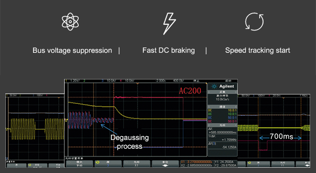
1. Excellent bus voltage suppression to avoid the over-voltage alarm when the inverter accelerates or decelerates too fast.
2. Fast DC braking, special software demagnetization processing, to ensure smooth and stable shutdown process without fluctuations.
3. The new generation of speed tracking start realizes zero waiting time and zero impulses current start.
Stable output, high accuracy
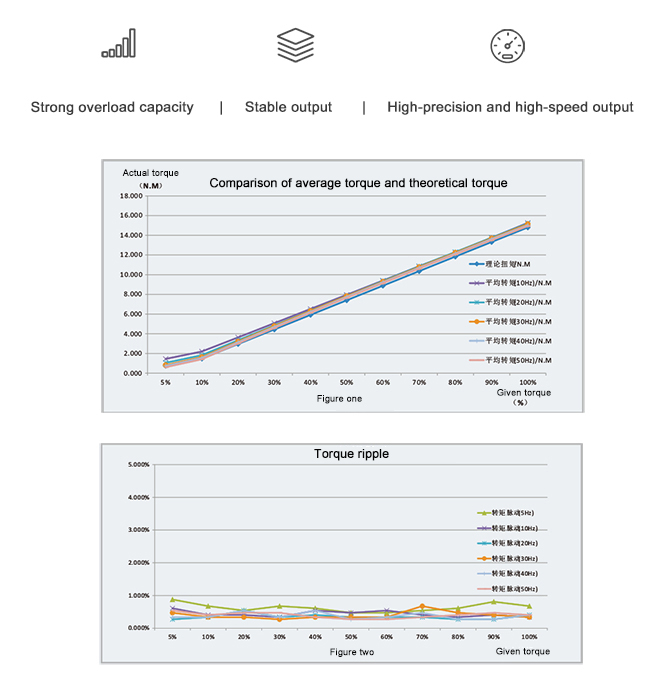
1. On the closed-loop vector mode, the torque linearity deviation is within 3%, the torque output is stable, and the low-frequency torque is large.
2. The output frequency under vector control is up to 600Hz, which can achieve high-precision speed output within 10 times the field weakening speed range.
3. Strong overload capacity, 60s at 150%, 10s at 180%, 0.5s at 200%.
4. Protect the torque limit and speed limit of the machine, and better protect the equipment safety under the premise of exerting the machine efficiency.
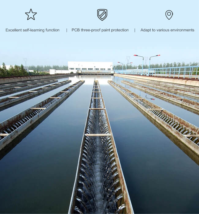
Adapt to the environment, flexible application
1. Motor parameter self-learning, static self-learning is comparable to dynamic self-learning, with no need to disassemble the load.
2. Instantaneous stop and non-stop, the inverter will not stop when the grid drops instantaneously, and the load will feedback energy to compensate for the voltage drop.
3. Coping with harsh environments more freely, the whole machine has a three-proof design, copper busbar plating, and PCB spraying three-proof paint.
Rich functions and reliable performance
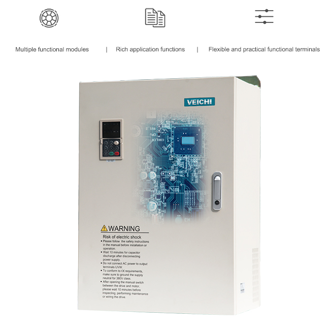
1. Built-in multiple groups of PID function modules, diverse selection of given and feedback sources, simple and practical.
2. Abundant application functions, command channel switching, running command binding, timing, counter, and other functions.
3. The terminal functions are flexible and practical, switch analog quantity, high-speed pulse input, and output.
Diversified expansion, outstanding ability
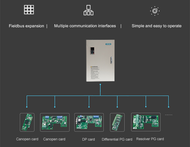
1. Support field bus expansion and PROFIBUS protocol can be supported through an optional DP card.
2. Provide a variety of communication excuses to realize RS485, DP, CAN, and CANopen communication.
3. IOT expansion card, high positioning accuracy, stable communication, compact and beautiful, easy to install.
4. PC software debugging, parameter rewriting, and monitoring, simple and easy to operate.
Industrial Applications for AC200 High Performance Vector Control AC Drive
Applications:Fans and pumps, printing and packaging equipment, textile equipment, air compressors, injection molding machines, machine tools, and other industries and equipment.
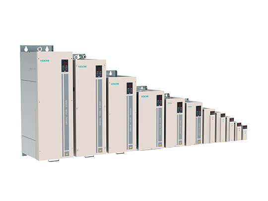
Specifications
| Single phase 220V 50/60Hz,Three-phase 220V 50/60Hz | 0.4kW~220kW |
|---|---|
| Three-phase 380V 50/60Hz | 0.75kW~710kW |
| Three-phase 660V 50/60Hz | 7.5kW~710kW |
| Three-phase 1140V 50/60Hz | 37kW~710kW |
| Voltage and frequency | Single-phase 220V 50/60Hz Three-phase 380V 50/60Hz; Three-phase 220V 50/60Hz Three-phase 660V 50/60Hz Three phase1140V 50/60Hz |
|---|---|
| Allow fluctuation | Voltage imbalance rate: <3%; Frequency: ±5%; Distortion rate meets IEC61800-2 requirements |
| Closing impulse current | Less than rated current |
| Power factor | ≥0.94 (with DC reactor) |
| Inverter efficiency | ≥96% |
| The output voltage | Output under rated conditions: 3-phase, 0~input voltage, error less than 5% |
|---|---|
| Output frequency range | Type G: 0~600Hz |
| Output frequency accuracy | ±0.5% of maximum frequency value |
| Overload capacity | Type G: 150% rated current for 1 minute, 180% rated current for 10 seconds, 200% rated current for 0.5 seconds |
| Motor control mode | V/F control without PG, vector control without PG, V/F control with PG, vector control with PG |
|---|---|
| Modulation | Optimize space vector PWM modulation |
| Carrier frequency | 0.7~16.0kHz |
| Speed control range | Vector control without PG, rated load 1:100; vector control with PG, rated load 1:1000 |
| Steady-state speed accuracy | Vector control without PG: ≤2% of rated synchronous speed; vector control with PG: ≤0.05% of rated synchronous speed |
| Starting torque | Vector control without PG: 150% rated torque at 0.5Hz; Vector control with PG: 200% rated torque at 0Hz |
| Torque response | Vector control without PG: <20ms; Vector control with PG: <10ms |
| Frequency accuracy | Digital setting: maximum frequency×±0.01%; analog setting: maximum frequency×±0.2% |
| Frequency resolution | Digital setting: 0.01Hz; Analog setting: maximum frequency×0.05% |
| DC braking capability | Starting frequency: 0.00~50.00Hz; Braking time: 0.0~60.0s; Braking current: 0.0~150.0% of rated current |
|---|---|
| Torque boost | Automatic torque increase 0.0%~100.0%; manual torque increase 0.0%~30.0% |
| V/F curve | Four methods: linear torque characteristic curve, self-set V/F curve, reduced torque characteristic curve (1.1~2.0 power), square V/F curve |
| Acceleration and deceleration curve | Two ways: linear acceleration and deceleration, S curve acceleration and deceleration Four sets of acceleration and deceleration time, the time unit is 0.01s, the longest is 650.00s |
| Rated output voltage | Using the power supply voltage compensation function, the rated motor voltage is 100%, which can be set in the range of 50 to 100% (the output cannot exceed the input voltage). |
| Automatic voltage adjustment | When the grid voltage fluctuates, it can automatically keep the output voltage constant |
| Automatic energy saving operation | Under V/F control mode, the output voltage is automatically optimized according to the load to realize energy-saving operation |
| Automatic current limit | Automatically limit the current during operation to prevent frequent over-current fault trips |
| Instantaneous power failure processing | In case of instantaneous power failure, uninterrupted operation is realized through bus voltage control |
| Standard function | PID control, speed tracking and restart after power failure, jump frequency, frequency upper and lower limit control, program operation, multi-speed, RS485, analog output, frequency pulse output. |
| Frequency setting channel | Keyboard digital setting, keyboard potentiometer, analog voltage terminal VS, analog voltage/current terminal AI, analog current terminal AS, communication setting and multi-channel terminal selection, main and auxiliary channel combination, expansion card, can be switched in various ways. |
| Feedback input channel | Voltage terminal VS, voltage/current terminal AI, current terminal AS, communication setting, pulse input PUL |
| Run command channel | Operation panel setting, external terminal setting, communication setting, expansion card setting |
| Input command signal | Start, stop, forward and reverse rotation, jog, multi-speed, free stop, reset, acceleration and deceleration time selection, frequency setting channel selection, external fault alarm. |
| External output signal | 2 relay outputs, 1 collector output, 1 AO output can be selected as 0~10V or 4~20mA output, 1 AO output can be selected as 0~10V or 4~20mA or frequency pulse output output. |
| Protective function | Overvoltage, undervoltage, current limit, overcurrent, overload, electronic thermal relay, overheating, overvoltage stall, data protection, fast protection, input and output phase loss protection. |
|---|
| LED display | Single line 5-digit digital tube display,it can monitor 1 inverter status Dual-line 5-digit digital tube display,it can monitor the status of 2 inverters |
|---|---|
| Parameter copy | The function code information of the inverter can be uploaded and downloaded to realize fast parameter copy |
| Status monitoring | All parameters of the monitoring parameter group such as output frequency, given frequency, output current, input voltage, output voltage, motor speed, PID feedback quantity, PID given quantity, module temperature, etc. |
| Error alarm | Overvoltage, undervoltage, overcurrent, short circuit, phase loss, overload, overheating, overvoltage stall, current limit, data protection damaged, current fault operating status, historical fault. |
| Installation site | If the altitude is lower than 1000 meters, derating for use above 1000 meters, derating by 1% for every 100 meters No condensation, icing, rain, snow, hail, etc., solar radiation less than 700W/m2, pressure 70~106kPa |
|---|---|
| Temperature and humidity | from -10℃ to +50℃, derating can be used above 40℃, the maximum temperature is 60℃ (no-load operation) 5% ~ 95%RH(No condensation) |
| Vibration | When 9~200Hz,5.9m/s2(0.6g) |
| Storage temperature | -30~+60℃ |
| Installation mode | Wall-mounted, vertical cabinet |
| Protection degree | IP20 |
| Cooling method | Forced air cooling |
Downloads
| File Name | Type | Language | File Type | Update | Download |
|---|---|---|---|---|---|
| Introduction of Internet of Things | Catalog | English | 2018-02-04 | 2.4MB | |
| Frequency Drive Catalog | Catalog | English | 2018-03-27 | 3.53MB | |
| AC200 Series Frequency Inverter Maunal V1.3 | Manual | English | 2018-03-05 | 3.27MB | |
| ACDP01.GSD | Manual | English | ZIP | 2018-12-25 | 2KB |
| AC Series Drive Software V1.6 | Software | English | ZIP | 2022-03-11 | 31.9MB |


 Leave a Message