Global - English
 Spanish - Español
 French - Français
 Russian - Pусский язык
 Chinese - 中文
 Korean - 한국어
 Vietnamese - Tiếng Việt
VFD Installation Instructions
When you buy a new VFD for your control system, then the next step is installing VFD. In order to make it work with the best performance, there are some important items what you need to pay attention to during the process of VFD installation. In this article, we will show you the machinery installation instructions and electric installation instructions.
1. VFD Installation Environment
Its installation environment is very important to maintain its best working performance for a long time. So before you install it, please make sure the installation environment meets the following requirements:
a. Install place: please install VFD indoor where is without direct sunshine.
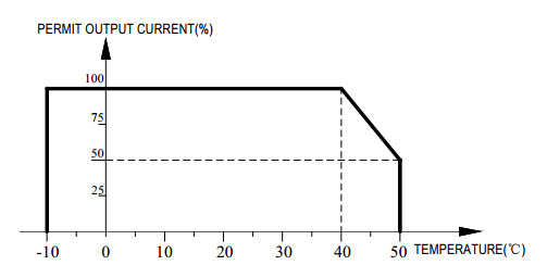
b. Temperature: please install it in environment which is -10 ~ +40°C, and the storing temperature is -20 ~ +60°C.
When the temperature is beyond the allowed limits, please follow the below chart for derating use:
c. Humidity: please make sure the humidity is less than 95% with no condensation.
d. Surrounding environment: please install VFD in place meeting the following requirements.
(1) Please make sure the installation environment with no oil mist, corrosive gas, flammable gas and dust.
(2) Please install it on place without metal dust, oil, water and etc. Besides, please do not install VFDs on flammable material such as wood.
(3) Please place it where there is no radioactive material as well as flammable material.
(4) Please install it on place where there is no poisonous gas or liquid.
(5) Please make sure the installation place is of no salt erosion and direct sunshine.
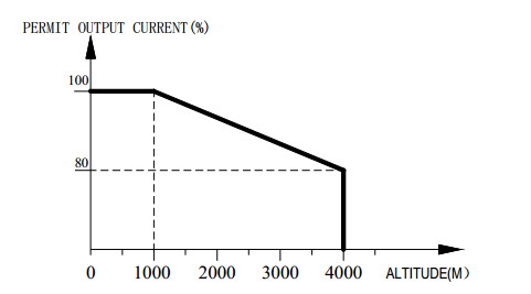
e. Altitude: less than 1000 meters.
When the altitude is beyond the allowed limits, please follow the below chart for derating use:
f. Vibration: when 10 to 20Hz, 9.8m/s2 .when 20 to 55Hz, 5.9m/s2 .
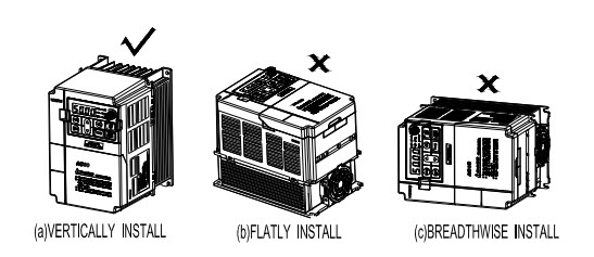
g. VFD installation and cooling: it must be installed vertically, instead of horizontal installation. In order to keep the perfect cooling effect, please separately install the high heating equipments such as braking resistor. The braking resistor cannot be installed at the air-in port.
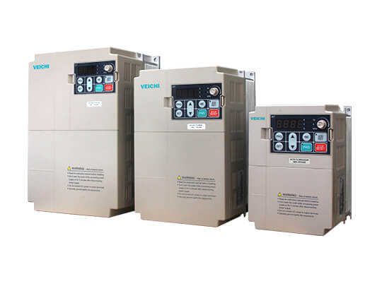
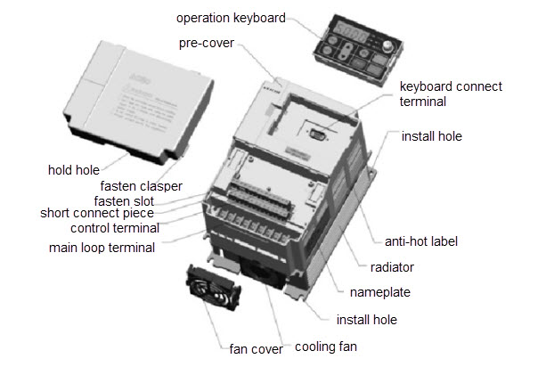
2. Mechanical Installation of VFD
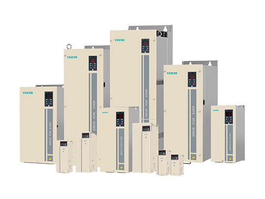
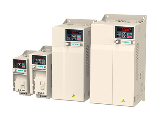
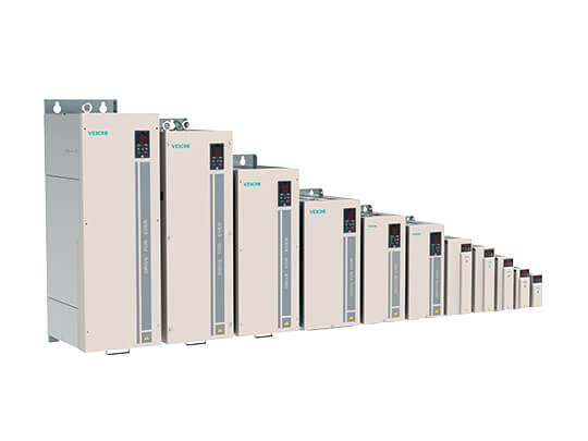
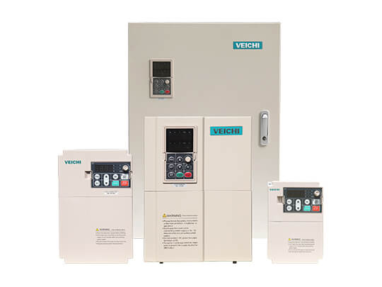
a. Main components:
b. Installation direction: in order to maintain the good cooling effect, please install it vertically just as the below image shows.
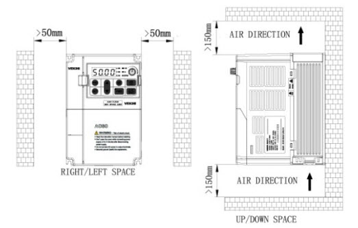
c. Installation space:
(1) For single machine installation, please install it as the following image shows. In order to maintain the perfect ventilation and heat dissipation, the back should be sticked to the wall.
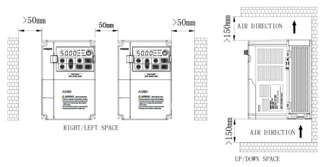
(2) For multiple installation in one cabinet, please make sure there is enough space between them just as the following image shows.
3. Electric Installation of VFD
a. Safety attentions:
The following warnings should be obeyed in order to maintain secure use and outstanding performance:
(1) To prevent the casualty and unstable performance, it must be earthed reliably.
(2) Only trained professional person can perform VFD installation and wiring.
(3) Please do operate with power offer status.
(4) Before installation, please power off all related equipments and the main circuit DC current should be dropped to secure level, and then operate after 5 minutes.
(5) The control cable, power cable and motor cable must be separated. They cannot be in the same cable trough or cable rack.
(6) Please do not test the insulation of VFD with HV insulation test equipment.
(7) When do insulation test for VFD and its peripheral equipments such as filter, reactor and more, please firstly test the insulation with 500V megohmmeter with the insulation resistance more than 4MO.
b. Standard wiring diagram
The following diagram is of Veichi AC70 vector inverter series:
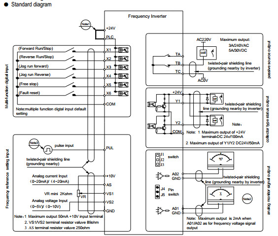
Note:
(1) NPN or PNP transistor signal can be selected as input of multi-function input terminal(X1~X6). Inverter built-in power supply (+24V terminal) or external power supply (PLC terminal) can be chosen as bias voltage. Factory setting +24V short connect with PLC.
(2) Analog monitor output is special output of meters such as frequency meter, current meter, voltage meter and etc. It cannot be used for control operations such as feedback control.
(3) As there are multi pulse styles, please refer to the line connect mode description details.
If you need to learn more details about VFD installation for each series, please go to specific product page to download PDF user manual for further learning. If you have any difficulty upon installing VFD, please do contact us instantly.