 Global - English
 Spanish - Español
 French - Français
 Russian - Pусский язык
 Chinese - 中文
 Korean - 한국어
 Vietnamese - Tiếng Việt
Servo System for CNC Machine
Foreword
CNC lathe is a high-precision, high-efficiency automated machine tool. It has a wide range of processing properties, processing linear cylinders, slanted cylinders, circular arcs and various threads. It has various compensation functions such as linear interpolation and circular interpolation, and has played a good economic effect in mass production of complex parts. CNC lathe is the most widely used CNC machine tool in China with the largest coverage, accounting for about 25% of the total number of CNC machine tools.
The birth of CNC lathes is of epoch-making significance for human machining. The manufacturing of workpieces has also moved to the road of high volume, high precision and high stability. For a country, the proportion of CNC machine tools in all metal cutting equipment, it is an important parameter to measure its level of automation. It is of great significance to the development of the national economy and the strength of the country.
CNC lathes
Digital control machine tool - CNC machine tool, its English name is CNC MACHINE TOOLS. It is an electromechanical device that is automatically processed using a programmed machining program. There are many types of CNC machine tools, including CNC lathes, CNC grinders, CNC boring machines, CNC planers, CNC milling machines, CNC vertical lathes, etc., It also includes vertical turning and milling machining center, horizontal milling and boring machining center, gantry boring and milling machining center, CNC turning and milling machining center, CNC slitting machine and other CNC machine tools for composite machining. In addition, in recent years, emerging EDM machines, laser cutting machines, water cutting machine tools, wire cutting machine tools, parallel CNC machine tools, and automated compound machine tool production lines have also developed rapidly.
CNC machine tool
What is a CNC lathe?
A lathe is a machine tool that mainly turns a rotating workpiece with a turning tool. Mainly used for machining shafts, discs, sleeves and other workpieces with a rotating surface, it is the most widely used type of machine in the mechanical manufacturing and repairing plant. CNC lathe, also known as CNC lathe, it is a computerized digital control lathe, and which is a high-precision, high-efficiency automated machine tool. It has a wide range of processing properties, processing linear cylinders, slanted cylinders, circular arcs and various threads. It has various compensation functions such as linear interpolation and circular interpolation, and has played a good economic effect in mass production of complex parts. CNC lathe is the most widely used CNC machine tool in China with the largest coverage, accounting for about 25% of the total number of CNC machine tools. CNC machine tools are mechatronics products integrating mechanical, electrical, hydraulic, pneumatic, microelectronics and information technologies. It is a working machine with high precision, high efficiency, high automation and high flexibility in mechanical manufacturing equipment.
CNC machine tools
Development status of lathe
As the master machine of all metal processing machines, the lathe has created a modern lathe with a screw drive tool holder since 1797. Since the British mechanical inventor Mozli created a modern lathe with a screw drive tool holder, it has greatly advanced the development of the mechanical processing industry. The development of lathes in the world has gone from ordinary lathes to hydraulic semi-automatic, automated, to numerical control, until today's intelligent, networked development process, the relationship between machines and people has become more and more simplified, from relying on proficiency to ensure the quality of the workpiece to input only the NC program, high-quality, high-efficiency products can be obtained, and the lathe becomes more and more humanized, in the adaptation to working conditions, process requirements, specialization, environmental protection and other aspects have stepped into the modern hall. Western countries, including Germany, the United States, and Japan, have developed earlier lathes, especially CNC lathes, and have accumulated rich experience in lathe development. Their machine tools maintain a leading edge in terms of technical level, precision retention, composite high speed machining and a wide range of accessories. Although China started late, it has experienced the stages of technology introduction, digestion and re-innovation. It has absolute advantages in the low-end market, and it is still lacking in high-end, especially high-precision, high-speed and high-complexity. The development history of external CNC lathes, combined with the current maturity of technology, the development of CNC lathes reflects the following characteristics:
CNC lathes
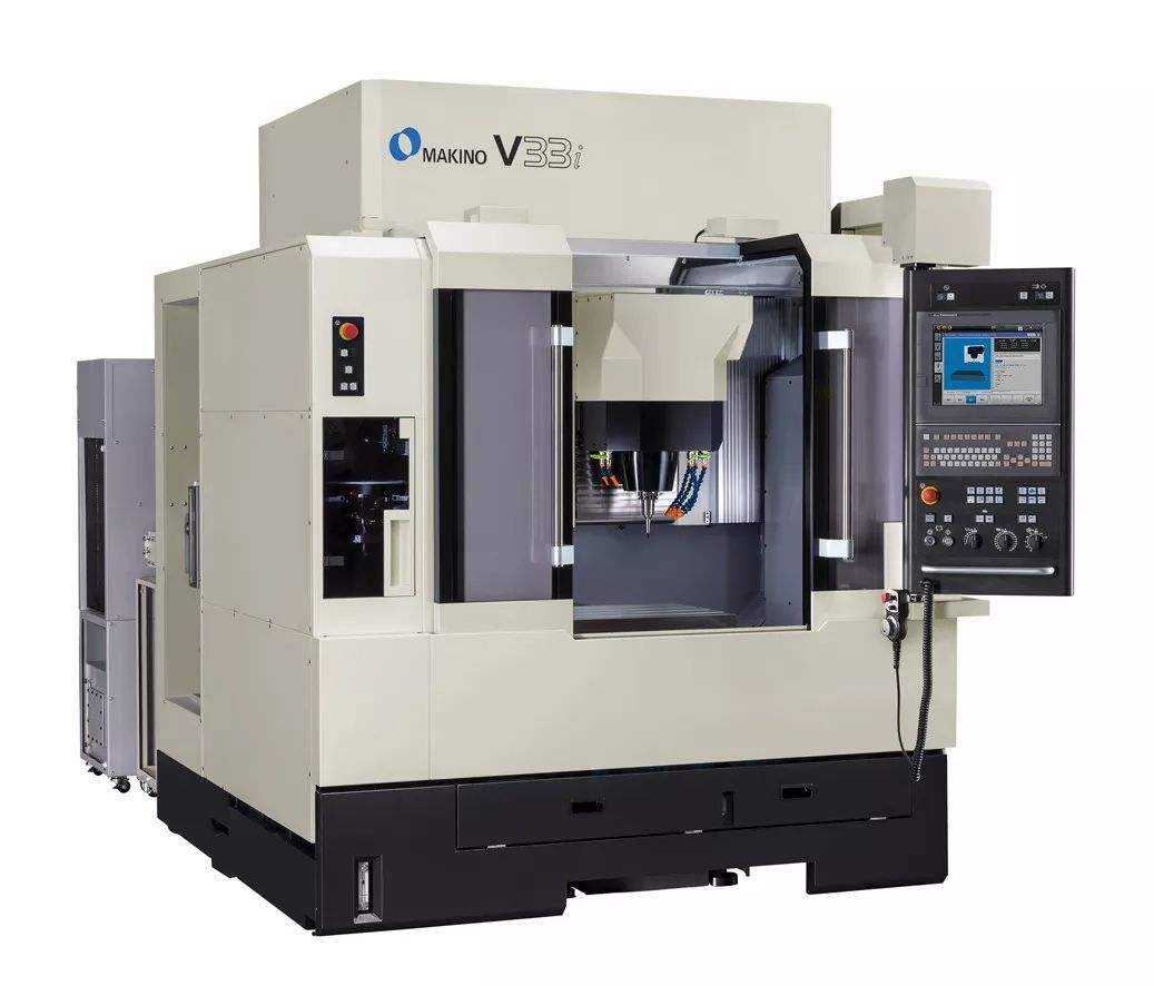
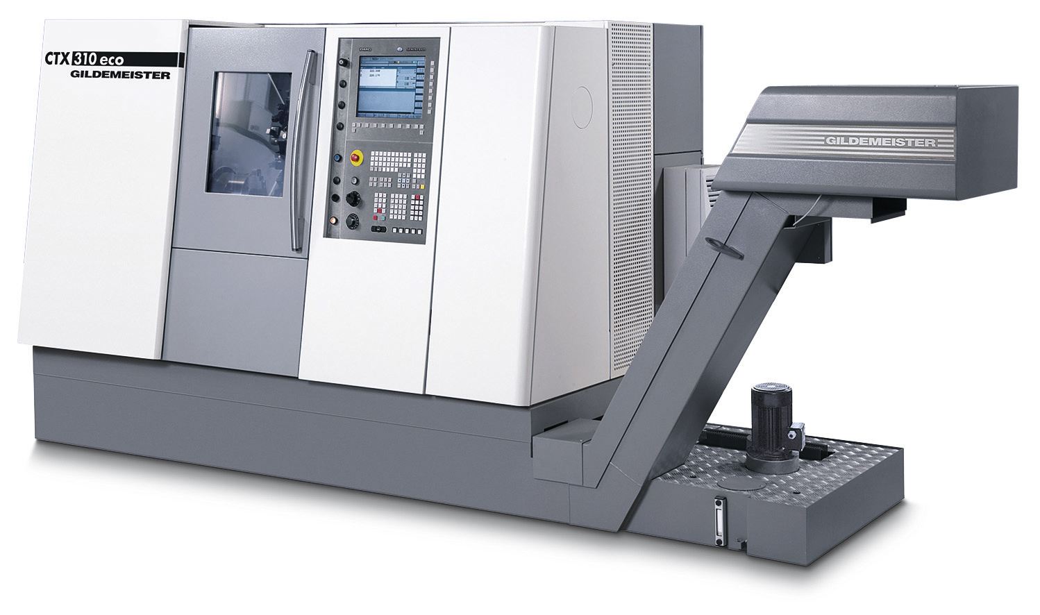
(1) High-speed, high-precision, and composite processing have become mainstream. In the field of general processing, the common lathes and economical CNC lathes currently used on the market are processed at the IT7 level, and their spindle speed is low and the rapid traverse rate is low. It will be gradually eliminated in the next 5-10 years. And replaced by higher-speed, higher spindle speeds and faster-moving line-type machine tools, the revolution in the entire CNC lathe era has been achieved in the United States, Germany, Japan, South Korea and Taiwan. Gradually implemented in developing countries such as China and India. In many scientific research, aerospace and military fields, due to the stricter processing precision, shape and position error and contour error requirements of workpieces, the demand for composite machining of machine tools is obvious. For example, the rotor of an aircraft engine often needs to be installed once, and the processing of various complex surfaces, holes and grooves is completed at one time to ensure the accuracy. It is necessary to have the ability of the machine tool to perform composite machining, and the precision of the workpiece can be ensured by the precision of the machine tool. This type of machine is represented by the DMG CTX series CNC machining center.
(2) Online error detection and compensation functions are gradually becoming popular. With the innovative development of CNC system technology, internet technology and sensor technology, we have the ability to realize online detection and compensation of workpieces on CNC lathes. In the actual machining process, due to the force and thermal deformation of the machine components, the machining accuracy is reduced. The online detection and compensation technology will solve this problem well, and these high-end technologies have been popularized with general-purpose devices. The US Haas series is mainly used.
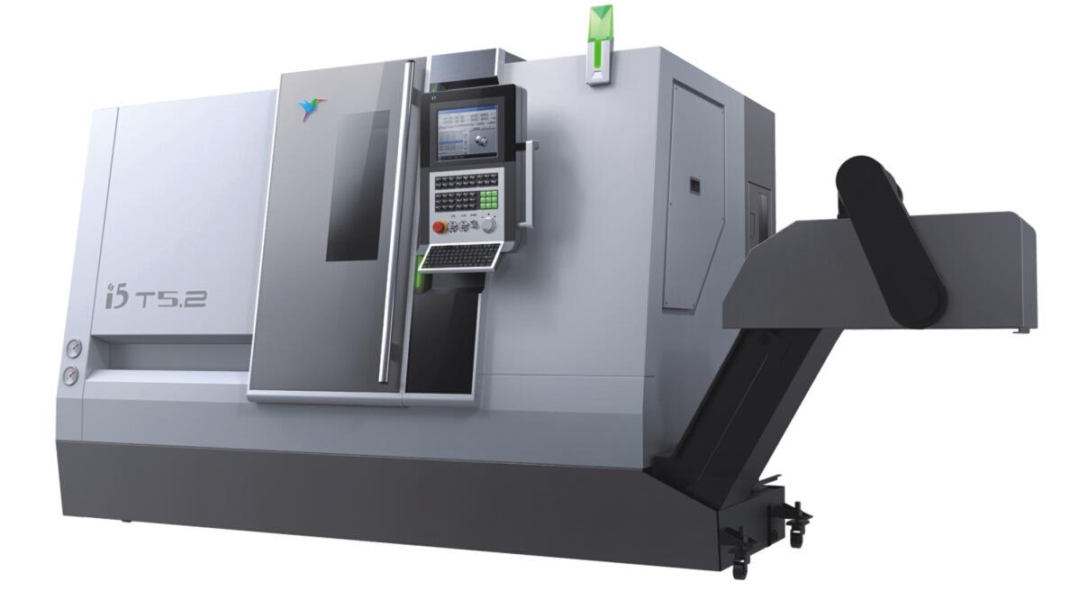
(3) Intelligent, networked and flexible. The development of the internet provides unlimited possibilities for the development of CNC machine tools. With the popularity and maturity of the network, machine tools with Internet interfaces will become the protagonists of the times. With the realization of the IOT and interoperability through the network, the future machine tools can communicate with each other, real-time monitoring, real-time feedback, analysis and utilization of machine position status, workpiece status and other data, greatly improving production efficiency. Relying on data can also enable remote network manufacturing and customized manufacturing to achieve a true industrial internet. This series of machine tools is represented by the i5 series machine tools of Shenyang Machine Tool.
CNC Machine Tool
Motor parts of CNC lathes
1. Tool holder
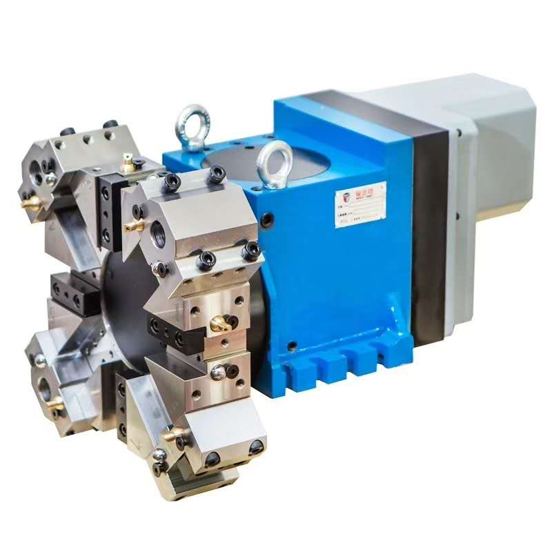
Tool holder
As a key function of the CNC lathe, the power tool holder has a very important function, mainly used to realize the function of clamping the tool, stocking the tool and automatically changing the tool. CNC tool holders are usually divided into low, medium and high in the market. The classification is mainly determined by the use occasion. The low-grade tool holder generally only uses electric power as the power, which is simply called the electric tool holder. Since only the torque of the motor is used as the source of the force of the rotation torque of the tool holder, it cannot carry too many functions, but the structural simplicity also makes this The low-end electric tool holder has a strong carrying capacity, and its low-grade simplicity determines that it cannot be applied to high-precision and multi-demand machines, and can only be used on economical and simple machine tools. The mid-range tool holder has a certain improvement, and there are many types, mainly hydraulic tool holder, servo tool holder and double-selection electric tool holder. According to the name of the tool holder, the hydraulic tool holder is mainly powered by hydraulic motor or hydraulic cylinder. The servo uses servo motor as the power source. It has higher requirements in control and precision, and it is faster and repeats more accurate positioning. This mid-range tool holder is widely used on ordinary machine tools due to its applicability and price. Compared with the mid-range tool holder, the high-grade CNC tool holder has a better performance level, mainly in terms of precision retention and high-precision machining. Its high automation is also the development direction of high-grade tool holders. For advanced CNC machine tools with high precision requirements.
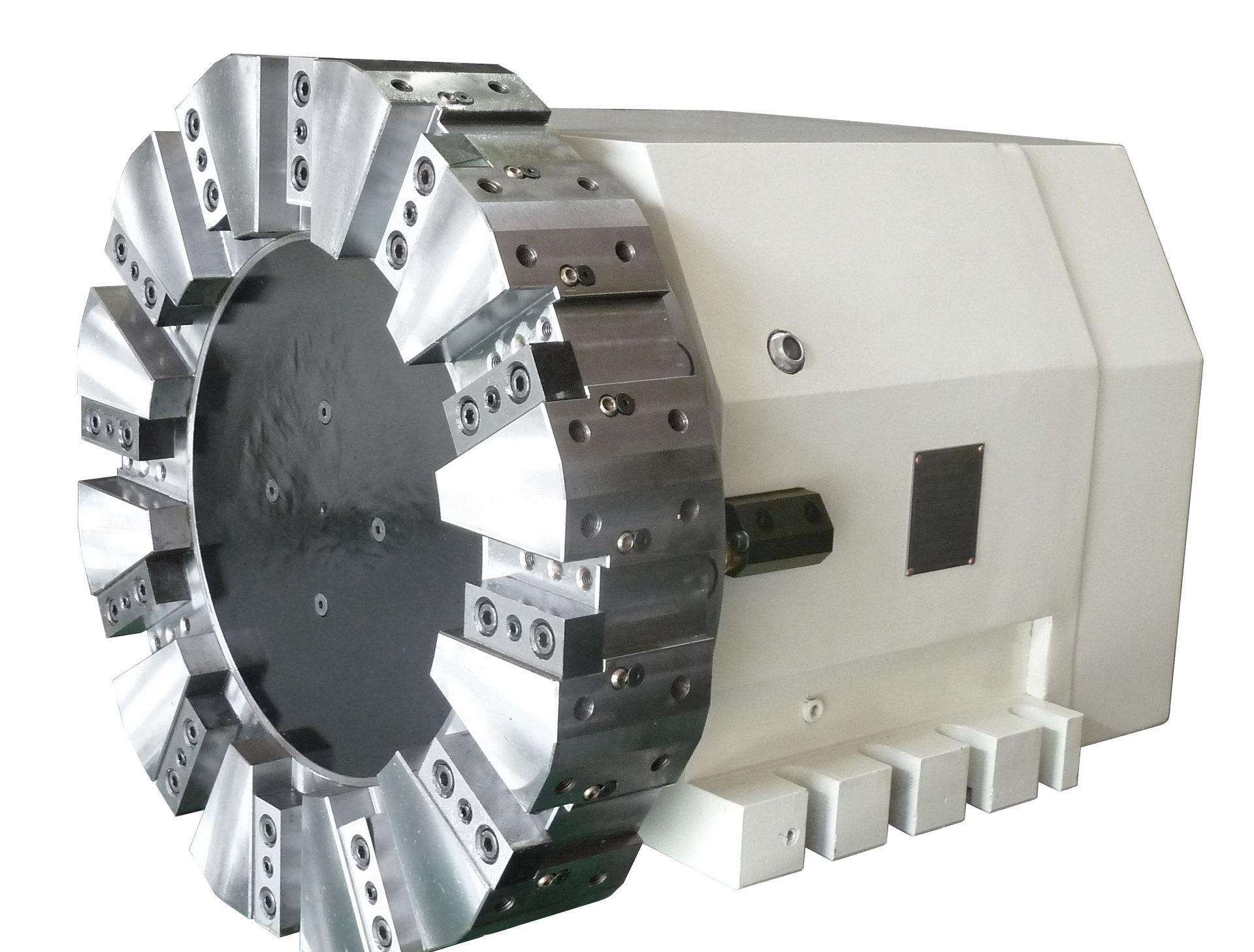
Hydraulic tool holder
The development history of the power tool holder dates back to the 1980s. With more than 30 years of development, as a key component of CNC machine tools, its importance has been paid more and more attention. The reliability and performance of the power tool holder are used. The stability on the top plays an important role in the reliability level of the whole machine. Today's tool holders in the world are concentrated in Germany, Italy, the United Kingdom and other more developed countries in Europe. Due to the long history of development, the accumulation of technology is relatively strong, the research team is also very first-class, and the tool holders they design and manufacture are reliable. Higher performance. The world's most famous tool holders include Schott in Germany, Balafa in Italy and Dupumadik, which occupy the mid to high-end market.
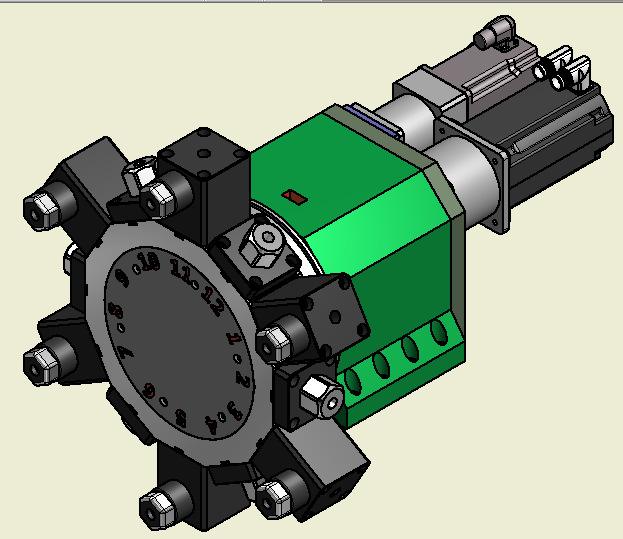
Power knife holder
Different tool holder manufacturers distribution table
| Market segmentation | Mainstream manufacturer | |
| Low-end market | Double power tool holder | SCHOTT, Dipma, Yantai Global, Shenyang Machine Tool |
| Middle and high-end market | Double power tool holder | SCHOTT, Dipma, Balafati |
| High-end market | Single power tool holder | SCHOTT, Dipma, Germany EWS, Germany LARU |
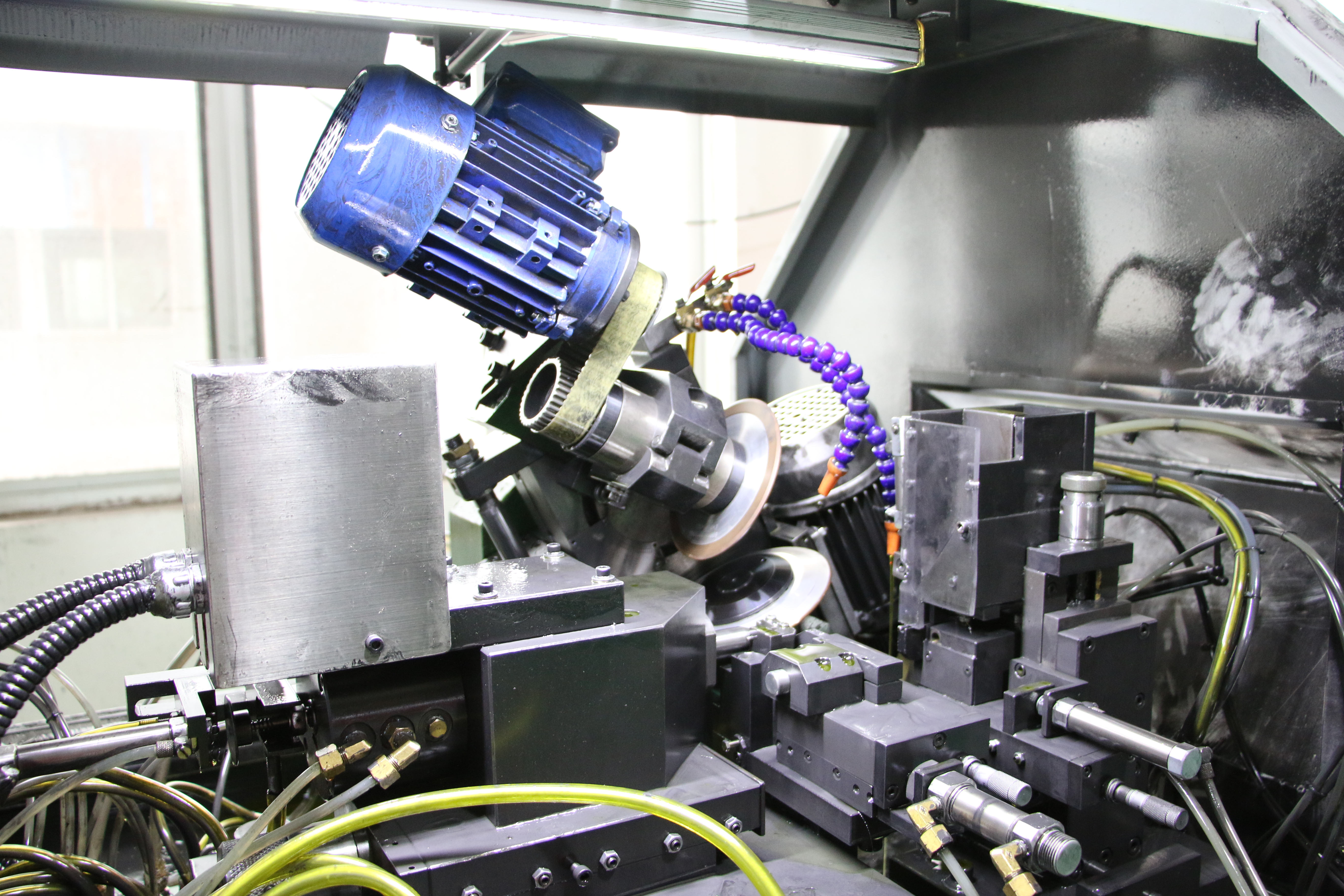
2. Feed servo
The servo drive system consists of a three-ring structure of position control, speed control and current control.
1) The current loop
The current loop is the innermost loop of the system. It is the bottom data sampling link of the whole Servo System. The shorter the sampling period of the discrete current loop, the higher the servo stiffness can be, and the better the servo control performance will be. The current loop is the innermost loop, so the current loop is the fundamental of control and the most direct performer of all control. Broadly speaking, the ultimate goal of servo adjustment is to ensure that no matter how high or low speed the machining is, it is necessary to ensure the stability of the current as much as possible (the current harmonic component of the current loop output is small), and do not fluctuate too much. The current response speed is fast. Only the stability of the current can guarantee the stability of the torque, and finally the final machining effect can be ensured. In addition, due to the high-speed processing cycle, the current loop also bears the detailed detection of the control anomaly. The current loop as the innermost loop must satisfy the higher response period than the speed loop and the position loop, so that accurate real-time control can be performed due to the change of the rotational speed. The AC frequency, that is, it can keep up with the command processing sent by the speed loop and respond in time.
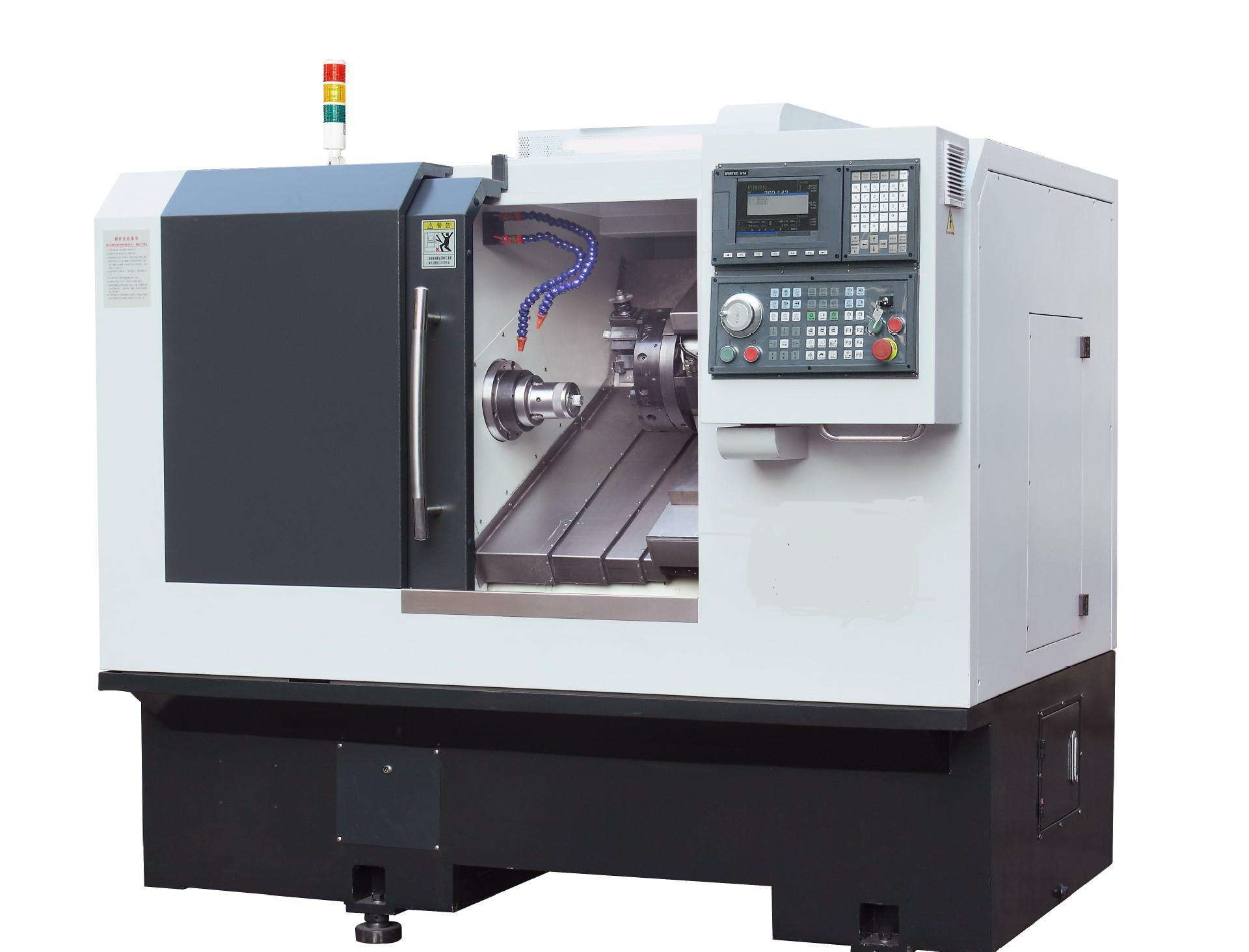
Slanting lathe solution
2)Speed loop
The speed loop ensures that the motor speed is consistent with the command value, eliminating the influence of load torque disturbance and other factors on the motor speed. The speed command is compared with the actual motor speed of the feedback. The difference is directly generated by the speed regulator to generate the q-axis command current to control the acceleration, deceleration or uniform speed of the motor, so that the actual speed of the motor is consistent with the command value.
The speed loop is the intermediate link between the current loop and the position loop. Reasonably increasing the speed loop is the core of the entire servo commissioning. The speed loop uses the entire current loop as the controlled object. Torque is the product of speed and inertia. To ensure torque stability, speed and reasonable load inertia ratio are fundamental. Therefore, the role of the speed loop is to ensure the stability of the speed. The speed to load inertia ratio directly affects the stability of the current loop. One of the most critical parameters for servo adjustment is the speed loop gain (Kv).
The speed loop gain is the difference magnification of the given speed compared to the feedback speed. Obviously the larger the multiple, the higher the resolution of the speed change. The higher the resolution, the stronger the ability to discriminate and reverse the speed fluctuations (because the essence of negative feedback is to constantly correct the difference until it is zero), this ability to reverse the speed is very critical, it means the anti-interference ability of this system to the external load, the greater the speed gain, the stronger the anti-interference ability of the system to the outside, the stronger the ability to suppress the speed fluctuation, the better the smoothness is (without vibration) ). Therefore, the larger the speed loop gain, which represents the precise speed control ability, represents the precise torque force, which represents the best surface smoothing characteristics. Together with the position loop, it represents the best responsiveness of the machine.

VEICHI servo drive
3) Position loop
The fundamental task of the position loop is to enable the actuator to accurately track position commands, which can generate speed commands for the motor and accurately position and track the motor. By setting the target position compared with the actual position at which the motor is accurately positioned, the position of the motor is used to generate the speed command of the motor. When the given amount varies randomly, the system can track and reproduce the given amount accurately and accurately. As can be seen from the block diagram of the servo drive system, the position loop is the outermost ring inside the three rings and is the final adjustment object. Controls all objects including current loops and speed loops.
In general, the current loop and the speed loop are determined first, and the position loop is finally determined. Therefore, after the position command after interpolation, the position loop is the most important final determinant to ensure that the machining result meets the requirements. To evaluate the processing performance of a machine tool, mainly in the surface finish and contour accuracy of the machined parts, and the contour accuracy is determined by the position loop from the system point of view. After the input command of the position loop is ensured, the difference is amplified with the feedback position returned by feedback, and the position error is obtained. Obviously, similar to the speed loop gain, the position loop gain describes the ability to accurately resolve position changes. Its role is to describe the static accuracy and dynamic tracking performance of the system. The larger the position loop benefit KP setting, the higher the discriminating ability and the torsion ability of the position change, the mechanical hysteresis will be greatly improved, and the dynamic follow performance will be stronger. With the high response of the speed loop, the positioning accuracy is finally improved.
The development of the servo system has gone through several stages
In the early 1960s, the numerical control machine tool used a hydraulic servo system. Compared with the conventional DC motor at that time, the liquid and servo system had a short response time, and the servo component outputting the same torque had a small outer shape. However, the hydraulic servo system has the disadvantages of large heat generation, low efficiency, environmental pollution and inconvenient maintenance.
In the mid-1960s, the open-loop system consisting of a small-power servo-type stepper motor and a hydraulic torque amplifier was once widely used in CNC machine tools. The most representative of these is the Japanese company's electro-hydraulic pulse motor servo system. However, due to the complexity of the system structure and poor reliability.
CNC turning and milling machine program
In the late 1960s, small inertia DC motors were widely used on CNC machine tools. The small inertia DC motor makes the structure of the motor more complicated due to the addition of the intermediate gear transmission, which is prone to wear, increase the transmission gap, and affect the transmission accuracy.
In the 1970s, the American company GETTYS first developed a large inertia DC motor, which is usually referred to as a wide-speed DC motor. It has a wide speed range and can be connected directly to the lead screw. It greatly simplifies the matching with the inertia of the machine feed moving parts. Since the 1970s, large inertia DC motors have been widely used in various types of CNC machine tools and have achieved good results.
CNC machine tools
Since the 1980s, with the development of large-scale integrated circuits, power electronics, computer control technology, especially the computer to make a major breakthrough in the vector control technology of the magnetic field of AC motors, people have been trying to replace DC with AC motors for a long time. The idea of motor application in speed regulation and servo control is realized. The AC servo system retains almost all the advantages of the DC system, and has excellent technical characteristics such as wide speed regulation range, high speed accuracy and good dynamic response characteristics, and inherits many excellent performances inherent in the AC motor itself.
In recent years, many processing equipments using linear motor feed servo systems have appeared internationally. At the 1993 Hanover Europe Machine Tool Fair, Germany exhibited the world's first linear machining center with a linear motor, which kicked off the linear motor servo system. Linear servo is the ideal driving mode for high-speed and high-precision CNC machine tools. It will be a prominent feature of the next generation of CNC machine tools, both in foreign countries and in domestic research and exploration.
CNC machine tools
Requirements for servo feed systems
The servo system is an automatic control system with mechanical parameters (position, speed, acceleration) as the controlled quantity. Its basic requirement is that the output of the system can respond quickly and accurately to changes in the command input. The basic requirements for the servo system are:
1) Good stability means that the system can reach a new or return to the original equilibrium state after a short adjustment process under the given input or external disturbance.
2) The accuracy of a servo system is the accuracy with which the output can follow the input. As a precision machined CNC machine tool, the required positioning accuracy or contour machining accuracy is usually separated.
3) Good response is one of the indicators of the dynamic quality of the servo system, that is, the response of the tracking command signal is required to be fast, and the transition process time is required to be short, generally required to be within 200 milliseconds or even less than several tens of milliseconds; On the other hand, the frontier of the transition process is required to be steep, that is, the rate of increase is large.
4) Sensitivity: the sensitivity of the system to parameter changes is small, that is, the system can be greatly affected by the parameter changes. Immunity: the system should have good resistance to external load interference and high frequency noise.
5) The requirements for the mechanical transmission system; in order to ensure the transmission accuracy and work stability of the CNC machine feed system, when designing the mechanical transmission device, the following requirements are proposed:
(1) Transmission accuracy and positioning accuracy: The transmission accuracy and positioning accuracy of the CNC machine feed transmission device play a key role in the machining accuracy of the parts. Regardless of the point position, linear control system, or contour control system, transmission accuracy and positioning accuracy are the main indicators to characterize the performance of CNC machine tools.
(2) The response speed should be fast: the workbench should be able to track the commands sensitively and accurately within the specified speed range, and perform single-step or continuous movement without loss or multi-step phenomenon during operation.
(3) No-gap transmission: The transmission clearance of the feed system generally refers to the reverse clearance, that is, the reverse dead zone error, which exists in the transmission pairs of the entire transmission chain, directly affecting the machining accuracy of the CNC machine tool; therefore, it should be eliminate the drive clearance and reduce the reverse dead zone error.
(4) Good stability and long life: stability is the most basic condition for the servo feed system to work properly, especially in the case of low-speed feed without creeping, and can adapt to changes in the applied load without resonance. The life of the so-called feed system mainly refers to the length of time for which the CNC machine tool transmission accuracy and positioning accuracy are maintained, and the ability of each transmission component to maintain its original manufacturing precision.
(5) Easy to use and maintain: the structural design of the feed system should be easy to maintain and maintain, minimizing the amount of maintenance work to improve the utilization of the machine.
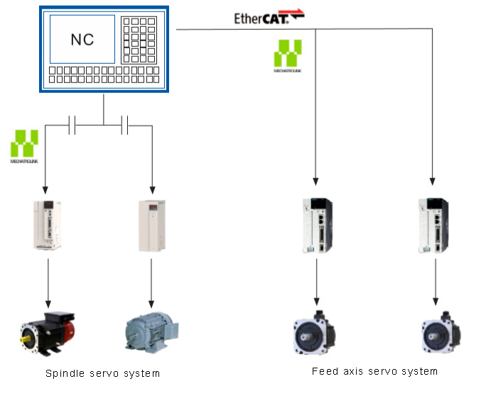
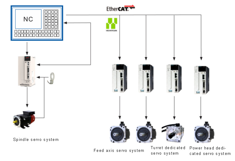
Spindle servo system
Features and requirements of CNC lathe spindle drive system:
The function of the spindle control system is to drive the spindle according to the program requirements. In the machining mode of the CNC lathe, the spindle mainly drives the workpiece to rotate, and cooperates with the feed servo drive shaft to complete the cutting motion. The accuracy and speed adjustment of the spindle position of the CNC lathe is not as high as that of the servo system. Therefore, the common AC asynchronous motor is used for the actuators. The expensive permanent magnet AC servo motor is rarely used. Generally, the inverter + AC asynchronous motor is used. "The method of vector control and encoder speed detection." With the continuous upgrading of the industry, "spindle servo drive + spindle servo motor + external encoder" is more and more widely used in the oblique body CNC milling and compounding machine, which can meet the requirements of general precision parts machining and turning thread, and adjust It is convenient and convenient, and the cost of construction is relatively low. It is widely used.
CNC lathe spindle drive system
The spindle movement of the CNC lathe is to transmit the main cutting force, and the power consumed accounts for about 60% of the total power of the machine. Therefore, the drive system must have sufficient power, rigidity, and sufficient torque to maintain sufficient torque at low speeds. The different spindle speed requirements of different machining processes, such as turning threads, roughing and finishing, require a wide speed range of the spindle.
The spindle servo system is also like the feed servo drive. It has three rings, but the accuracy and response requirements are not as high as the requirements of the feed servo. Generally, the spindle servo motor is equipped with incremental 2500 photoelectric encoders. The manufacturer is adapting to a rotary transformer as a feedback component in response to a relatively large vibration field.
CNC lathe spindle drive system
There are 3 ways to mechanically drive the CNC lathe spindle
(1) Segmented stepless speed change. The spindle motor drives the spindle to rotate through the finite gear drive. This transmission mode is suitable for large CNC machine tools, especially for powerful cutting.
(2) Belt drive shifting. The spindle motor drives the spindle rotation through the synchronous belt transmission mode. This transmission mode is suitable for small and medium-sized CNC machine tools, especially for occasions with high requirements for vibration resistance;
(3) The motor is driven directly. The spindle motor directly drives the spindle rotation through the coupling or directly uses the electric spindle. This transmission method is suitable for small CNC machine tools, especially for high-precision machining.
The servo system of CNC machine tools is one of the key systems for machine axis motion, including feed motion, spindle motion and position control. Its performance has an important influence on the repeated positioning accuracy, dynamic response characteristics of the CNC machine tool, and the maximum free-range motion speed. At the same time, the development of servo system has had an inestimable impact on the development of CNC machine tools.